Elevator Shaft and Hoistway Construction: Dimensions, Fire Ratings, and Pit Requirements | Projul
Building an elevator shaft is one of those scopes that can make or break your project schedule. Get the dimensions wrong by two inches and you are looking at a change order that ripples through every floor. Miss a fire rating detail and the inspector will shut you down. This guide walks through the real-world requirements for elevator hoistway construction so you can plan it right the first time.
What Exactly Is a Hoistway?
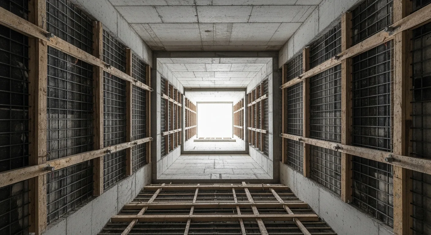
The hoistway is the vertical enclosure that houses the elevator car, counterweights, guide rails, and associated equipment. It runs from the pit floor at the bottom to the overhead structure at the top. The terms “hoistway” and “elevator shaft” are used interchangeably on most job sites, though “hoistway” is the formal code term you will see in ASME A17.1 and the IBC.
The hoistway is not just an empty box. It is a fire-rated, structurally engineered, precisely dimensioned enclosure that must accommodate mechanical equipment, electrical runs, ventilation, and safety systems. Every inch matters.
Key Codes and Standards
Before you pour a single yard of concrete, get familiar with the governing documents:
- ASME A17.1 / CSA B44 (Safety Code for Elevators and Escalators) covers the mechanical and safety requirements for the elevator system itself.
- IBC Chapter 30 (Elevators and Conveying Systems) covers building code requirements for the hoistway enclosure.
- IBC Section 713 specifies shaft enclosure fire-resistance ratings.
- NFPA 72 addresses fire alarm and smoke detection in hoistways.
- ADA / ICC A117.1 governs accessibility requirements for elevator cars and landings.
Your local jurisdiction may amend any of these, so always verify with your building official before finalizing drawings.
Hoistway Dimensions: Getting It Right
Inside Clear Dimensions
The hoistway inside clear dimensions depend on the elevator type, capacity, cab size, and door configuration. Here are typical ranges for common installations:
Passenger Elevators (2,500 lb capacity):
- Width: 6 feet 8 inches to 7 feet 0 inches
- Depth: 5 feet 6 inches to 6 feet 2 inches
Passenger Elevators (3,500 lb capacity):
- Width: 7 feet 0 inches to 7 feet 8 inches
- Depth: 6 feet 2 inches to 6 feet 10 inches
Freight Elevators (6,000 lb capacity):
- Width: 9 feet 0 inches to 10 feet 0 inches
- Depth: 8 feet 0 inches to 10 feet 0 inches
Service/Hospital Elevators (4,000 to 5,000 lb):
- Width: 7 feet 6 inches to 8 feet 6 inches
- Depth: 8 feet 0 inches to 9 feet 6 inches
These numbers are starting points. Every elevator manufacturer publishes detailed hoistway layout drawings that specify exact requirements down to the fraction of an inch. Get those drawings early in the design phase, not after you have already poured the shaft walls.
Critical Clearances
Several clearances within the hoistway are non-negotiable:
- Running clearance: The gap between the elevator car or counterweight and the hoistway wall must be maintained per ASME A17.1. Typically 3/4 inch minimum on sides.
- Car-to-counterweight clearance: Usually 1 inch minimum between the car and counterweight when they pass each other.
- Door clearance: The hoistway opening must accommodate the door frame, sill, and operator hardware. Flush front walls need careful coordination.
- Guide rail brackets: These mount to the hoistway walls and need solid backing. Plan your embed plates or through-bolts during wall construction.
Plumbness Tolerances
Hoistway walls must be plumb within tight tolerances, typically 1/4 inch in 10 feet and no more than 1 inch total over the full height. For high-rise shafts, this is a real challenge. Use a plumb laser at every pour lift and check frequently. A shaft that drifts out of plumb will cause guide rail alignment problems, car rubbing, and potential safety issues.
Pit Construction
The elevator pit is the section below the lowest landing. It is one of the most detail-heavy parts of the job.
Pit Depth Requirements
Pit depth varies by elevator type:
- Hydraulic (standard): 4 feet 6 inches to 5 feet 0 inches
- Hydraulic (low-overhead): 2 feet 0 inches to 3 feet 0 inches
- Traction (geared): 5 feet 0 inches to 8 feet 0 inches
- Traction (gearless, high-rise): 8 feet 0 inches to 12 feet 0 inches
- MRL (machine-room-less): 4 feet 0 inches to 5 feet 6 inches
These depths are measured from the finished floor of the lowest landing to the pit floor. The structural slab below the pit floor needs to account for buffer loads and the weight of any hydraulic cylinder assemblies.
Pit Structural Requirements
The pit floor must support:
- Buffer impact loads (check ASME A17.1 for specific calculations based on elevator speed and weight)
- Hydraulic jack and cylinder assembly weight (for hydraulic elevators)
- Standing water weight if waterproofing fails and the sump pump is overwhelmed
- Worker loads during maintenance (minimum 300 psf live load per many specs)
Most pits are cast-in-place concrete with a minimum thickness of 8 inches, though 12 inches is common for heavier installations. Reinforce per structural engineer drawings, and do not skimp on rebar at the corners where walls meet the floor.
Waterproofing the Pit
Water in the elevator pit is one of the most common problems on completed buildings. Address it during construction:
- Exterior waterproofing membrane on the outside of the pit walls and floor. Bentonite sheets or liquid-applied membranes work well.
- Crystalline waterproofing admixture added to the concrete mix for self-sealing capability.
- Waterstops at all cold joints between pours.
- Sump pit and pump are required by code in most jurisdictions. The sump must be located where it will not interfere with elevator equipment. Coordinate the discharge piping route early.
- Interior sealant as a secondary barrier after curing.
Do not rely on a single waterproofing method. Belt and suspenders is the right approach when the alternative is a flooded elevator pit and an angry building owner.
Pit Ladder and Access
ASME A17.1 requires a permanent, fixed ladder in pits deeper than 35 inches. The ladder must extend at least 42 inches above the pit access door sill. Install a pit light switch and a GFCI outlet at the access point. These are easy items to miss during rough-in and painful to add later.
Fire Ratings and Enclosure Requirements
Wall Fire Ratings
Per IBC Section 713:
- 4+ stories served by the hoistway: 2-hour fire-resistance rating
- Under 4 stories: 1-hour fire-resistance rating
The fire rating applies to the walls, floor (pit slab), and the overhead structure. Hoistway doors at each landing must match the wall rating, meaning 1.5-hour doors for 2-hour shafts and 1-hour doors for 1-hour shafts (per IBC Table 716.1).
Common Wall Assemblies
- 8-inch CMU, fully grouted: Achieves 2-hour rating with most units. Verify with the CMU manufacturer’s UL listing.
- Cast-in-place concrete, 8 inches: Typically exceeds 2-hour rating depending on aggregate type.
- Metal stud with multiple layers of Type X gypsum: Possible for 1-hour rated shafts but not common for hoistways due to the need for structural attachment points.
For most commercial projects, CMU or concrete is the go-to choice. The walls need to support guide rail brackets, door frame anchors, and other equipment loads that gypsum assemblies struggle to handle.
Penetrations and Firestopping
Every penetration through the hoistway wall needs firestopping per ASTM E814. This includes:
- Electrical conduits for car calls, hall stations, and position indicators
- Telephone/intercom wiring
- Smoke detector wiring
- Sump pump discharge piping
- Machine room HVAC penetrations (for non-MRL installations)
Use listed firestop systems (UL or Intertek) and document every installation with photos. Inspectors will check these, and missing firestop is a common punch list item.
Hoistway Ventilation
Code Requirements
IBC Section 3004 addresses hoistway venting:
- Non-sprinklered buildings: Hoistways must be vented to the outside with openings at the top of the shaft. Vent area must be at least 3.5% of the hoistway cross-sectional area.
- Sprinklered buildings: Venting requirements are often reduced or eliminated, depending on the local code interpretation and the fire protection engineer’s design.
Smoke Control
In many jurisdictions, elevator hoistways in high-rise buildings require pressurization systems to prevent smoke migration. This involves supply fans, pressure sensors, and coordination with the fire alarm system. Get the mechanical engineer involved early because the ductwork and fan rooms need space that competes with other building systems.
Machine Room vs. Machine-Room-Less (MRL)
Traditional Machine Room
Hydraulic and older traction elevators need a dedicated machine room, usually located directly above the hoistway (traction) or adjacent to the pit (hydraulic). Key requirements:
- Minimum ceiling height per manufacturer specs (usually 8 feet clear)
- Floor loading capacity for motor, controller, and hydraulic power unit
- Adequate ventilation or HVAC to maintain equipment operating temperature (typically 55 to 95 degrees F)
- Code-compliant lighting and a lockable door
- Fire rating matching the hoistway enclosure
MRL Installations
Machine-room-less elevators place the motor and controller inside the hoistway, typically at the top. This saves significant floor space but requires:
- Larger overhead clearance above the top landing
- Access panels at the top floor for maintenance
- Careful coordination of the control cabinet location within the hoistway
- Dedicated electrical feeds routed to the top of the shaft
MRL is now the standard for most new low- to mid-rise commercial and residential buildings. Discuss the pros and cons with your elevator consultant before committing to either approach.
Structural Considerations
Loads on the Building Structure
The hoistway transfers significant loads to the building:
- Dead loads: Car weight, counterweight, guide rails, brackets, and all fixed equipment
- Live loads: Rated capacity plus code-required overload factors
- Impact loads: Buffer strikes, safety device activation
- Lateral loads: Guide rail reactions from off-center car loading and seismic forces
Your structural engineer needs the elevator manufacturer’s load data early in the design process. Rail bracket loads, buffer loads, and machine beam reactions are all specific to the model being installed.
Seismic Requirements
In Seismic Design Categories C through F, ASME A17.1 Section 8.4 requires seismic restraints for guide rails, counterweights, and machine room equipment. The hoistway structure must accommodate these additional loads. In high seismic zones, the guide rail brackets may need to be significantly heavier than standard installations.
Coordinating the Elevator Subcontractor
Elevator installation is almost always a specialty subcontract. Coordinate early and often:
- Pre-construction: Get manufacturer hoistway drawings and review them against the architectural and structural drawings. Resolve conflicts before construction starts.
- During shaft construction: Have the elevator sub inspect the hoistway at key milestones, especially after pit completion and before overhead pour.
- Rough-in coordination: Elevator electrical rough-in (traveling cables, car lighting, ventilation fans) must happen in sequence with the shaft construction.
- Testing and inspection: The elevator sub handles state inspections, but you need to provide a completed, clean hoistway with all required fire ratings, lighting, and electrical feeds in place.
Managing these coordination points across multiple trades is where good project management software pays for itself. Tools like Projul let you track submittals, schedule inspections, and keep every trade aligned on the same timeline. When you are juggling elevator, electrical, fire protection, and structural subs on a single shaft, having all your schedules and documents in one place saves hours of phone calls every week.
Common Mistakes to Avoid
After years of seeing hoistway construction go sideways, here are the most frequent problems:
Undersized hoistway: The architect drew the shaft based on one manufacturer’s specs, but the owner selected a different elevator. Always design with tolerance or confirm the equipment before finalizing dimensions.
Missing embeds: Guide rail bracket locations are specific and must be accurate within 1/4 inch. If you miss the embeds during a concrete pour, you are drilling and epoxying anchors later, which is expensive and sometimes insufficient for the loads.
Incomplete waterproofing: Water will find the pit. Assume it will happen and design accordingly. A sump pump without waterproofing is just managing a leak you could have prevented.
Late coordination: Waiting until the shaft is built to involve the elevator subcontractor guarantees problems. Their input during design prevents costly field modifications.
Forgotten utilities: Pit lights, GFCI outlets, sump pumps, phone lines, smoke detectors, and ventilation fans are all required. Create a hoistway utility checklist and verify every item before the elevator sub starts installation.
Inspection and Closeout
Elevator inspections are typically handled by the state or a third-party authorized inspector, not your local building official. The process usually includes:
- Rough inspection: Hoistway structure, fire ratings, and electrical rough-in
- Final inspection: Completed elevator installation, safety testing, load testing
- Certificate of operation: Issued after passing final inspection, required before the elevator can carry passengers
Keep all documentation organized from the start, including concrete test reports, firestop inspection records, waterproofing warranties, and elevator submittals. When inspection day arrives, having everything in order speeds up the process dramatically.
If you are looking for a better way to manage the documentation and scheduling that comes with complex vertical construction, request a demo of Projul and see how it handles multi-trade coordination on commercial projects.
Wrapping Up
Elevator shaft construction is detail work. The dimensions are tight, the codes are specific, and the coordination between trades is constant. But if you plan it properly, get the manufacturer involved early, and stay on top of your fire ratings and waterproofing, the hoistway scope goes smoothly.
Take the time to build a comprehensive checklist for your next elevator shaft project. Cross-reference ASME A17.1, the IBC, and your manufacturer’s hoistway drawings. And keep every trade on the same page with a project management system that actually works for construction. Check out Projul’s pricing to find a plan that fits your operation.
Frequently Asked Questions
What is the minimum pit depth for a hydraulic elevator?
What fire rating is required for elevator hoistway walls?
How thick should elevator shaft walls be?
Do elevator shafts need ventilation?
What are standard elevator shaft dimensions for a passenger elevator?
Can you build an elevator shaft with wood framing?
What is the overhead clearance requirement for an elevator?
How do you waterproof an elevator pit?
Related Articles

BIM Clash Detection: How to Catch Conflicts Before They Cost You on the Jobsite
BIM Clash Detection: How to Catch Conflicts Before They Cost You on the Jobsite Every contractor has a story about the...
Read More →
Asphalt Paving and Compaction Guide: Mix Types, Laydown Temperatures, and Quality Testing
Asphalt paving looks straightforward from a distance. A truck dumps material, the paver lays it down, and rollers...
Read More →
Construction Jobsite Wi-Fi & Connectivity Guide: Setting Up Reliable Internet in the Field
A practical guide to getting reliable internet on construction job sites. Learn about cellular hotspots, mesh networks,...
Read More →