Helical Pier Foundations: Installation, Load Capacity, and When to Use Them | Projul
Helical piers have gone from a niche foundation product to one of the most commonly specified deep foundation systems in residential and light commercial construction. If you are a contractor who has not worked with them yet, chances are good you will encounter them on a project soon. They show up in new construction on poor soils, foundation repair on settling buildings, and temporary support applications where future removal is needed.
This guide covers what helical piers are, how they work, when they make sense compared to other foundation options, and the practical details of installation that every contractor should understand.
What Is a Helical Pier?
A helical pier is a manufactured steel foundation element that consists of a central shaft with one or more helical bearing plates (helices) welded to the lower portion. It looks something like a large screw. The pier is rotated into the ground using hydraulic equipment, and the helical plates pull it down into bearing soil the same way a screw pulls into wood.
Once the pier reaches adequate bearing capacity, confirmed by installation torque, it is connected to the structure through a bracket assembly. The structure’s load transfers through the bracket, down the shaft, and into the soil through the helical plates.
The concept has been around since the 1830s, when Alexander Mitchell used screw piles to support lighthouses in tidal waters. Modern helical piers use high-strength steel, precision-manufactured helices, and engineered bracket connections that make them suitable for a wide range of structural applications.
How Helical Piers Work: The Torque-to-Capacity Relationship
The most important concept in helical pier installation is the correlation between installation torque and bearing capacity. As the pier advances through soil, the resistance encountered by the helical plates increases with soil density and strength. Harder, denser soil requires more torque to advance the pier.
This relationship is expressed through a torque correlation factor, often called Kt. The formula is straightforward:
Ultimate Capacity = Kt x Installation Torque
The Kt value is determined by the pier manufacturer based on shaft size and configuration. For a standard 1.5-inch square shaft residential pier, Kt is typically 10 ft-1. So if the pier is installed to a torque of 3,000 ft-lbs, the ultimate capacity is 30,000 pounds.
A factor of safety of 2.0 is standard practice, making the allowable working load 15,000 pounds in this example.
This torque-to-capacity method gives contractors and engineers a real-time verification of pier capacity during installation. Every pier on the project gets its capacity confirmed individually, which is a significant advantage over other foundation types where capacity is assumed based on soil borings at a few test locations.
Types of Helical Piers
Round Shaft Piers
Round shaft helical piers use a hollow tubular steel shaft, typically ranging from 2-7/8 inches to 8-5/8 inches in diameter. They offer higher buckling resistance than square shaft piers and are the standard choice for commercial applications, larger structures, and situations with soft or loose upper soils where lateral support is minimal.
Round shaft piers also have higher individual capacities, commonly rated from 50,000 to over 200,000 pounds depending on size and configuration.
Square Shaft Piers
Square shaft piers use solid steel bar, most commonly 1.5-inch or 1.75-inch square. They are the workhorses of the residential foundation repair industry. Square shafts are stiffer per unit of cross-sectional area than round shafts, making them efficient in compression. They cost less than round shaft piers and are easier to handle in tight residential settings.
Typical capacities for 1.5-inch square shaft piers range from 20,000 to 50,000 pounds ultimate.
Combination Shaft Piers
Some applications use a square shaft lead section with helices and a round shaft upper section. This gives the benefit of the square shaft’s soil-cutting ability at the bearing depth while providing the round shaft’s buckling resistance through weak upper soils.
Helix Configuration
Helix Sizing
Helical plates typically range from 6 to 16 inches in diameter. Larger helices provide more bearing area and higher capacity in a given soil, but they also require more torque to install. The helix diameter is selected based on the target soil bearing stratum and required capacity.
Number of Helices
Most helical piers have 2 to 4 helices. Multi-helix configurations provide higher capacity because each helix acts as an individual bearing plate. The spacing between helices is typically 3 times the diameter of the lower helix, which prevents the pressure bulbs from overlapping and ensures each plate develops its full capacity independently.
Helix Pitch
Standard helix pitch is 3 inches per revolution, which is consistent across manufacturers. This uniform pitch ensures the pier advances smoothly without augering soil out of the way. The pier cuts through soil rather than displacing it, which minimizes disturbance to surrounding ground.
When to Use Helical Piers
New Construction on Poor Soils
When a geotechnical report identifies inadequate bearing capacity at shallow depths, helical piers provide a cost-effective way to reach deeper bearing strata. They are particularly competitive with drilled shafts and driven piles for lighter structures where individual pier loads are under 100,000 pounds.
Foundation Repair
This is the highest-volume application for helical piers. Settling foundations caused by expansive clay, fill soils, organic decomposition, or changes in moisture content can be stabilized and often lifted back toward their original position using helical piers. The piers bypass the problem soils and bear on stable material below.
Tiebacks and Soil Retention
Helical anchors, which are essentially helical piers installed at an angle, are widely used for tieback support of retaining walls, sheet pile walls, and soldier pile walls. The helices develop pullout resistance in bearing soil, providing a tension anchor for the wall system.
Underpinning Existing Structures
When new construction requires excavation near an existing building, helical piers can underpin the existing foundation before excavation begins. This is common in urban infill projects where adjacent buildings need protection during basement or foundation construction.
Temporary Structures
Since helical piers can be removed by reversing the rotation, they work well for temporary buildings, construction trailers, solar panel ground mounts, and any application where the foundation may need to be removed in the future.
Equipment Foundations
Mechanical equipment pads, generator foundations, light pole bases, and sign foundations are all common applications. Helical piers can be installed quickly with minimal vibration and no curing time, so equipment can be set the same day.
Installation Process
Step 1: Review the Design
Before mobilizing to the site, review the helical pier plan including pier locations, required capacities, minimum installation torque, shaft and helix sizes, and bracket types. Verify that the specified equipment matches the job requirements and that underground utility locations have been identified and marked.
Step 2: Position Equipment
Helical piers are installed with hydraulic drive heads attached to mini excavators, skid steers, or specialized installation machines. Position the equipment so the drive head can access each pier location. In tight residential settings, a compact excavator with a 3,000 to 5,000 ft-lb drive head is the standard setup.
Step 3: Start the Lead Section
Place the lead section (the bottom piece with the helices) at the pier location and begin advancing it into the ground. The drive head applies continuous rotation at low RPM, typically 5 to 15 revolutions per minute. Crowd force from the excavator arm helps start penetration in hard surface soils.
Step 4: Add Extension Sections
As the lead section advances below grade, remove the drive head, add an extension section, and reconnect the drive head. Extensions are typically connected with bolted couplings. Continue advancing the pier, adding extensions as needed until reaching the target torque.
Step 5: Monitor Torque
Torque is monitored continuously using a pressure gauge on the hydraulic drive motor. Digital torque monitoring systems provide more accurate readings and can log data for documentation. Record the torque at each foot of installation depth to create a torque log for the engineer’s review.
Step 6: Verify Final Torque
When the pier reaches the target installation torque, hold it at that depth and verify the torque reading is consistent over the final few revolutions. Erratic torque readings may indicate the pier is transitioning between soil layers rather than bearing in a consistent stratum.
Step 7: Cut and Cap or Bracket
For new construction, the pier shaft is cut to the design elevation and a pier cap or base plate is welded or bolted on for the structure to bear on. For foundation repair, a bracket assembly is attached to the existing footing and connected to the pier shaft. Foundation repair brackets allow the structure to be lifted by pushing the bracket up the pier shaft with hydraulic jacks.
Step 8: Document Everything
Create a pier installation log that records pier number, location, shaft configuration, helix sizes, installation depth, final torque, and any notable conditions encountered during installation. This documentation is required for engineer acceptance and building department inspection.
Soil Considerations
Favorable Soil Conditions
Helical piers perform best when there is a competent bearing layer within economical reach. Stiff clays, dense sands, glacial till, and weathered rock are all excellent bearing strata. The ideal condition is soft or problematic soil in the upper zone with a clearly defined bearing layer at a predictable depth.
Challenging Soil Conditions
Cobbles and boulders: Large stones can deflect helical plates and damage helix edges. If the geotechnical report indicates significant cobbles, consider ground improvement or alternative foundation types.
Very soft soils extending to great depth: If there is no competent bearing layer within 50 to 75 feet, helical piers may not be practical. The number of extensions required makes installation slow and costly.
Highly corrosive soils: Soils with very low pH, high sulfate content, or high chloride content can accelerate corrosion of the steel pier. Hot-dip galvanization provides good protection in most conditions, but severely corrosive environments may require additional protection measures.
Caving or flowing soils: Loose, saturated sands that flow during installation can make advancement difficult and reduce capacity. Grout-filled round shaft piers are sometimes used in these conditions.
Helical Piers vs. Other Deep Foundation Options
vs. Drilled Shafts (Caissons)
Drilled shafts require large drilling equipment, temporary casing in unstable soils, concrete placement, and curing time. Helical piers install with smaller equipment, require no concrete, and can accept load immediately. Drilled shafts have higher individual capacities for very heavy structural loads, but helical piers are often more economical for loads under 100,000 pounds per pier.
vs. Driven Piles
Driven piles generate significant noise and vibration during installation, which can be problematic near existing structures and in urban environments. Helical piers install with virtually no vibration and minimal noise. Driven piles are generally more cost-effective for very high production rates on open sites where noise and vibration are not concerns.
vs. Push Piers
Push piers are driven into the ground using the weight of the existing structure as reaction force. This means they only work for foundation repair on structures heavy enough to provide adequate reaction. Helical piers do not rely on structure weight, so they work on both new construction and repair applications of any size. In soft soils, helical piers can also reach greater depths more reliably.
Load Testing
For critical applications, static load tests verify that helical piers perform as predicted by the torque-to-capacity method. ASTM D1143 covers compression load testing procedures, and ASTM D3689 covers tension (pullout) testing.
Quick load tests are the most common field test method. The pier is loaded in increments, typically 5% to 10% of the anticipated failure load, with settlement readings taken at each increment. The test continues until failure or until the required proof load is achieved.
Most projects do not require load testing on every pier. Testing is typically performed on 1% to 5% of production piers, with the remainder accepted based on installation torque correlation.
Common Installation Mistakes
Not monitoring torque continuously. Some installers only check torque at the end of installation. Continuous monitoring reveals soil conditions at every depth and helps identify problems before they become costly.
Ignoring torque fluctuations. If torque spikes and then drops, the pier may have hit a hard layer and then punched through into softer material. The final bearing stratum needs to show consistent torque over multiple revolutions.
Over-torquing. Exceeding the rated torque for the pier shaft can twist off the shaft or damage couplings. Know the torque limits for your equipment and pier components.
Installing too fast. High RPM can heat the helix plates and reduce their effectiveness. Keep rotation speed below 15 RPM and reduce speed in hard soils.
Inadequate documentation. Missing or incomplete pier logs create problems during inspection and can lead to costly disputes. Record data for every pier, every time.
Cost Factors
Helical pier costs depend on several variables.
Pier length and shaft size. Deeper installations require more extension sections. Larger shafts cost more per foot. Typical residential repair piers run $150 to $350 per linear foot installed, while commercial round shaft piers can run $30 to $80 per linear foot for material alone.
Number of piers. Higher pier counts allow better equipment utilization and lower per-pier mobilization costs.
Access conditions. Tight sites, interior installations through existing floors, and low-headroom conditions all increase labor time and cost.
Bracket types. Foundation repair brackets are more expensive than simple new construction pier caps. Specialty brackets for specific foundation types add cost.
Engineering and testing. Design engineering, load testing, and special inspection add cost but also add confidence in the foundation system.
For typical residential foundation repair, total installed costs including brackets and lifting usually run $1,500 to $3,500 per pier. Commercial projects vary too widely to generalize, but helical piers are often 15% to 30% less expensive than drilled shafts for equivalent load requirements.
How Projul Helps With Helical Pier Projects
Helical pier projects require tracking equipment, crew certifications, torque logs for every pier, inspection coordination, and documentation that engineers and building departments will review carefully. Projul’s construction project management software gives contractors a single platform to manage scheduling, track installation data, store documentation, and communicate with engineers and inspectors without shuffling paper between the truck and the office.
Final Thoughts
Helical piers are a proven, reliable deep foundation system that every foundation contractor should understand. They are not the answer for every project, but for the right applications, they offer installation speed, immediate load capacity, year-round installation capability, and real-time capacity verification that few other foundation systems can match.
The key to success is matching the right pier configuration to the site conditions, maintaining proper installation technique, documenting everything thoroughly, and working with engineers who understand how to design helical pier systems. If you are considering adding helical pier installation to your company’s service offerings, start with manufacturer training and consider bringing on an experienced installer to mentor your crews through the first several projects. The learning curve is manageable, and the market demand is growing steadily.
Frequently Asked Questions
How deep do helical piers need to be installed?
What loads can a helical pier support?
Can helical piers be installed in winter?
How long do helical piers last?
Are helical piers better than push piers for foundation repair?
Do helical piers require a soils report?
What equipment is needed to install helical piers?
Can helical piers be removed and reused?
Related Articles

BIM Clash Detection: How to Catch Conflicts Before They Cost You on the Jobsite
BIM Clash Detection: How to Catch Conflicts Before They Cost You on the Jobsite Every contractor has a story about the...
Read More →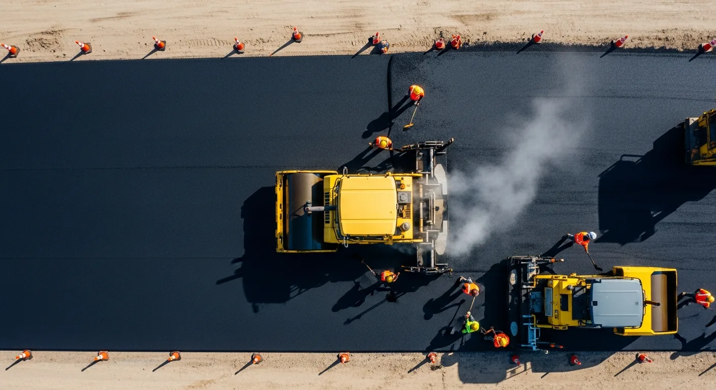
Asphalt Paving and Compaction Guide: Mix Types, Laydown Temperatures, and Quality Testing
Asphalt paving looks straightforward from a distance. A truck dumps material, the paver lays it down, and rollers...
Read More →
Construction Jobsite Wi-Fi & Connectivity Guide: Setting Up Reliable Internet in the Field
A practical guide to getting reliable internet on construction job sites. Learn about cellular hotspots, mesh networks,...
Read More →