Overhead Crane Runway Beam Installation Guide
Overhead crane installation is some of the most demanding structural steel work in industrial construction. The runway beams that carry the crane have to be straight, level, and properly spaced within tight tolerances, and they have to stay that way under thousands of load cycles. Get the runway wrong and you are dealing with premature rail wear, crane skew, structural fatigue, and safety problems that get worse with every lift.
This guide covers the full scope of crane runway beam installation, from structural design basics through alignment procedures, rail systems, connections, and deflection requirements. Whether you are building a new crane bay or retrofitting an existing building, these are the details that make the difference between a runway that works for decades and one that causes headaches from day one.
Understanding the Crane System
Before getting into runway details, it helps to understand how the components work together.
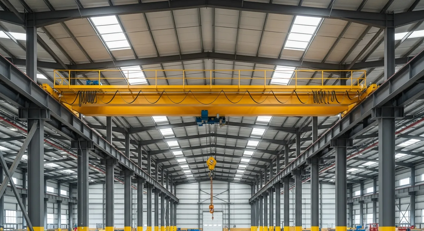
An overhead bridge crane consists of:
- Bridge: The horizontal structure that spans between two runways and carries the hoist
- End trucks: The wheeled assemblies at each end of the bridge that ride on the rails
- Hoist: The lifting mechanism that raises and lowers the load
- Runway beams: The building-mounted beams that support the crane rails
- Crane rails: The tracks mounted on top of the runway beams
The crane bridge travels along the runway (longitudinal direction), while the hoist trolley travels across the bridge (transverse direction). The runway beams must support all the forces generated by crane operation, including vertical loads, lateral loads, and longitudinal braking forces.
Crane Classifications
The Crane Manufacturers Association of America (CMAA) classifies cranes by duty cycle:
- Class A (Standby): Infrequent use, light loads
- Class B (Light): Light to moderate loads, low speed
- Class C (Moderate): Moderate loads at moderate speed, typical for general manufacturing
- Class D (Heavy): Heavy loads, higher speeds, frequent use
- Class E (Severe): Very heavy loads, high speed, continuous operation
- Class F (Continuous Severe): Critical service, extreme duty
The crane class directly affects the design requirements for the runway beams, connections, and columns. Higher duty classes require stiffer beams, stronger connections, and tighter deflection limits.
Runway Beam Design Basics
Runway beams are typically wide-flange (W-shape) steel sections, though built-up plate girders are common for heavy cranes or long spans. The beam design must address several types of loading simultaneously.
Vertical Loads
The primary vertical load is the crane wheel load, which includes the weight of the bridge, hoist, trolley, and lifted load. For design purposes, these loads are increased by an impact factor:
- 25 percent impact factor for cab-operated and pendant-operated cranes
- 10 percent for floor-operated cranes (AISC specification)
The maximum wheel load occurs when the hoist is positioned at one end of the bridge (closest to one runway) and the crane is carrying its rated capacity. This is the governing load case for runway beam design.
Lateral Loads
Lateral loads (horizontal forces perpendicular to the runway) result from crane skew, trolley acceleration, and accidental contact between the bridge and runway. CMAA and AISC specify lateral loads as a percentage of the lifted load plus trolley weight:
- 20 percent for cab and pendant operated cranes
- 10 percent for pendant operated only (some interpretations)
These lateral loads are applied at the top of the rail and must be resisted by the runway beam’s top flange, the cap channel (if present), and the connection to the supporting columns.
Longitudinal Loads
Longitudinal forces (along the runway direction) result from crane braking and acceleration. The longitudinal force is typically 10 percent of the total weight on the driven wheels, applied at the top of rail. These forces are transferred through the rail, rail clips, runway beam, and into the building’s longitudinal bracing system.
Fatigue Considerations
For cranes classified as CMAA Class C and above, fatigue is a critical design consideration. Runway beam connections, welds, and details must be designed for the expected number of load cycles over the structure’s service life.
Fatigue-prone details include:
- Welded stiffener connections to the runway beam web and flanges
- Cap channel welds to the top flange
- Bracket connections to columns
- Any weld detail on the tension flange of the runway beam
AISC’s fatigue provisions (Table A-3.1) categorize weld details by stress category (A through E’) and specify allowable stress ranges based on the number of load cycles.
Cap Channel and Lateral Bracing
The top flange of a runway beam takes lateral loads from the crane wheels. For anything beyond light-duty cranes, the top flange alone is not stiff enough. A cap channel adds lateral stiffness and provides a wider mounting surface for the crane rail.
Cap Channel Details
A cap channel (sometimes called a surge plate or surge girder) is typically a structural channel section welded continuously to the top flange of the runway beam. The channel flanges point outward, creating a wider platform for rail mounting.
Key details:
- The channel must be welded with a continuous fillet weld on both sides of the channel web to the beam flange
- The channel section is sized to resist the applied lateral loads in combination with the beam top flange
- The channel extends the full length of the runway beam, past the column connections
For heavy-duty cranes, a horizontal bracing truss (lacing) between the top flange and a parallel member may be used instead of or in addition to a cap channel. This provides greater lateral stiffness at the expense of more complex fabrication.
Runway Beam Connections
The connection between the runway beam and the supporting columns must transfer vertical reactions, lateral forces, and longitudinal forces while allowing for thermal expansion and contraction.
Simple Span vs. Continuous
Most crane runway beams are designed as simple spans between columns. Continuous beams (spanning over multiple columns) can reduce maximum moments and deflections but create complexities at the column connections, particularly for fatigue design. Simple spans are the standard approach for most applications.
Column Bracket Connections
The runway beam typically sits on a bracket or seat welded or bolted to the column face. Common connection types include:
Seated connections with a bottom seat bracket supporting the beam web, plus a top clip or keeper to prevent the beam from walking off the seat. The beam web is bolted to the seat through slotted holes to allow longitudinal movement.
Lug connections where a vertical plate (lug) welded to the column engages a slot or clearance space in the beam web. The lug transfers vertical and lateral loads while the slotted bolt holes allow thermal movement.
Direct bearing on column cap plates for top-running cranes on freestanding crane columns. The beam sits directly on the column top plate and is bolted through slotted holes.
Expansion and Contraction
A 200-foot runway in a building that sees a 100-degree Fahrenheit temperature range will experience about 1/2 inch of thermal expansion. This must be accommodated at the connections. Slotted bolt holes at one end of each beam span are the standard solution, with fixed connections at the other end or at a designated fixed point.
Connection Fatigue
Runway beam connections are among the most fatigue-sensitive details in the structure. Avoid welding directly to the tension flange of the runway beam whenever possible. Use bolted connections or attach to the web and compression flange. Any welds on the tension flange create stress concentrations that accelerate fatigue cracking.
Crane Rail Systems
The crane rail is the track that the crane end trucks ride on. Rail selection, installation, and maintenance directly affect crane performance and runway beam life.
Rail Types
ASCE rails are the most common for medium to heavy-duty cranes. They have a rounded head profile similar to railroad rail and are available in weights from 25 to 175 pounds per yard. Common sizes:
- ASCE 40 (40 lb/yd): Light duty, Class A-B cranes
- ASCE 60 (60 lb/yd): Moderate duty, Class B-C cranes
- ASCE 85 (85 lb/yd): Heavy duty, Class C-D cranes
- ASCE 104 and 135: Severe duty, Class D-F cranes
Square bar rail (typically 1-inch, 1-1/4-inch, or 1-1/2-inch square) is used for light-duty cranes, underhung cranes, and monorails. It mounts by welding intermittently to the beam flange, which is acceptable for low-cycle applications but creates fatigue concerns for higher duty cycles.
Flat bar rail (rectangular bar, wider than it is tall) is used for some light to moderate applications, particularly where crane wheel profiles require a flat running surface.
Rail Attachment
Rail clips are the standard attachment method for ASCE rail. Clips bolt to the beam top flange (or cap channel) and grip the rail base with a spring-loaded or forged clamp. The clips allow the rail to expand and contract independently from the beam while maintaining lateral alignment.
Key rules for rail attachment:
- Never weld rail directly to the beam flange for any crane class above Class A. Welding creates a rigid connection that transfers fatigue stresses directly into the beam flange.
- Rail clips should be spaced at a maximum of 24 inches on center for most applications, tighter for heavy-duty cranes.
- Use a resilient pad between the rail base and the beam flange to distribute wheel loads and dampen impact.
- Rail joints should be square-cut and butted tight, with joint bars bolted across the joint to maintain alignment.
Rail Alignment
Rail alignment must be set during installation and verified periodically. The alignment tolerances for crane rails are tight:
- Rail centerline to theoretical centerline: plus or minus 1/4 inch
- Rail straightness: 1/4 inch in any 40 feet
- Span between rail centerlines: plus or minus 1/4 inch at any cross-section
- Rail elevation: plus or minus 1/4 inch across the span; plus or minus 3/8 inch over the full runway length
- Rail joint elevation mismatch: 1/32 inch maximum
These tolerances are measured after the runway beams are loaded (self-weight plus rail weight) and before the crane is placed.
Deflection Limits
Deflection limits for crane runway beams are more stringent than for typical structural beams because excessive deflection causes crane tracking problems, accelerated wear, and structural fatigue.
Vertical Deflection
Maximum vertical deflection under rated crane load (not including impact):
- CMAA Class A-C: L/600 (AISC recommended minimum)
- CMAA Class D: L/800
- CMAA Class E-F: L/1000
Where L is the runway beam span between column supports.
Some crane manufacturers specify tighter limits. Always check the crane specifications; they may govern over the building code minimums.
Lateral Deflection
Lateral deflection of the runway beam top flange under lateral crane loads:
- General: L/400
- Tight tolerance cranes or automated systems: L/600 or tighter
Lateral deflection is often the controlling design parameter for runway beams, particularly for deep beams where the top flange is relatively narrow.
Column Deflection
The columns supporting the runway beams also deflect under crane loads. The lateral deflection at the top of the column (at the runway beam elevation) should be limited to:
- H/240 for general applications (where H is the height from the floor to the runway beam)
- H/400 for tight tolerance or high-cycle applications
Column deflection adds to the total misalignment the crane must accommodate, so both beam and column deflections must be considered together.
Installation Sequence
Proper installation sequencing is critical for achieving the required tolerances. Here is a typical installation sequence for a crane runway system.
Step 1: Column Erection and Alignment
Set crane columns to the correct elevation and alignment. Column base plates must be shimmed and grouted to achieve top-of-column elevations within 1/8 inch of theoretical. Column plumbness should be within 1/500 of the height.
For freestanding crane columns, temporary bracing holds the columns in position until the runway beams and longitudinal bracing are connected.
Step 2: Runway Beam Placement
Set runway beams on the column brackets. Verify that beam elevations match across the span and that the beam centerline alignment is correct. Bolt the beams to the brackets using the specified connection hardware but leave the bolts snug-tight (not fully tightened) until the full alignment survey is complete.
Step 3: Alignment Survey
Perform a detailed alignment survey of the runway beams using optical or laser surveying equipment. Measure:
- Top of beam elevation at each column and at mid-span
- Beam centerline location at each column
- Span dimension between beam centerlines at each cross-section
- Beam straightness (vertical and lateral)
Compare all measurements to the required tolerances. Adjust shims, connections, and beam positions as needed to bring everything into specification.
Step 4: Final Bolting
Once the alignment is confirmed, fully tension all connection bolts per the structural drawings. For slip-critical connections, use turn-of-nut, calibrated wrench, or direct tension indicating methods per AISC specifications.
Step 5: Rail Installation
Install crane rail after the beams are in their final position. Set rail to the specified alignment using rail clips. Verify rail alignment with a separate survey after installation.
Step 6: Crane Installation and Final Check
After the crane bridge is set on the rails, perform a final alignment check under the crane’s self-weight. The weight of the crane will cause some deflection in the runway beams; this deflection should have been anticipated in the pre-crane alignment targets.
Run the crane through its full range of travel and observe for smooth tracking, consistent wheel contact, and any signs of skew or binding. Make final rail adjustments as needed.
Longitudinal Bracing and Runway Stops
Longitudinal Bracing
The runway system needs longitudinal bracing to resist braking forces and to prevent the crane from pushing the runway beams along the building. Common bracing types include:
- Diagonal braces between runway columns in selected bays
- Horizontal bracing in the plane of the runway beam bottom flange
- Portal frames between crane columns
Locate the longitudinal bracing to transfer forces to the building’s main bracing system. Avoid bracing layouts that create thermal restraint.
Runway Stops
Crane runway stops (bumpers) are installed at each end of the runway to prevent the crane from traveling off the end of the rails. Stops must be designed to absorb the kinetic energy of the crane traveling at full speed. Common stop types include:
- Rubber bumpers for light-duty cranes
- Hydraulic bumpers for medium to heavy-duty cranes
- Spring bumpers for moderate applications
The runway beam and column at the stop location must be designed for the bumper impact load.
Runway Electrification
The crane needs electrical power delivered along the runway. Common electrification systems include:
- Conductor bars: Insulated copper or aluminum bars mounted along the runway beam, with collector shoes on the crane end trucks. This is the most common system for indoor cranes.
- Festoon cables: Flat cables suspended from a trolley system along the runway. Used for shorter runways and lighter cranes.
- Cable reels: Spring-loaded or motor-driven reels that pay out and retract cable as the crane moves. Common for outdoor cranes and long runways.
Conductor bar mounting brackets must be installed during the runway beam installation phase. Coordinate the bracket locations with the electrical contractor to ensure proper spacing and clearance from the crane end trucks.
Managing Crane Runway Projects
Crane runway projects involve tight coordination between the structural steel erector, the crane manufacturer, the electrical contractor, and the surveyor. Tolerances are tight, lead times are long, and sequencing matters.
Using a construction management platform like Projul keeps all the moving pieces organized. Track steel fabrication and delivery schedules, coordinate crane manufacturer site visits, document alignment surveys, and manage punch list items in one system.
For industrial construction teams building crane bays, Projul provides the scheduling, documentation, and communication tools to keep these complex projects on track. Check out the pricing or request a demo to see how it works for your team.
Maintenance and Inspection
Crane runways need regular inspection to catch wear and alignment drift before they become serious problems.
Routine Inspection Items
- Rail wear: Check rail head profile for flattening, cupping, or uneven wear. Uneven wear indicates alignment problems.
- Rail alignment: Survey rail alignment annually for high-cycle cranes. Compare to baseline measurements from installation.
- Rail clips: Check for loose, broken, or missing clips. Tighten or replace as needed.
- Connection bolts: Inspect runway beam connections for loose bolts, particularly at fatigue-sensitive locations.
- Beam flanges: Check for cracks in the beam top flange, particularly at welds and stiffener locations.
- Column plumbness: Re-survey column plumbness if alignment drift is detected.
- Runway stops: Inspect bumper condition and mounting bolt tightness.
Alignment Drift
Over time, crane runways can drift out of alignment due to foundation settlement, column deflection under repeated loading, connection wear, or thermal cycling. Annual alignment surveys (or more frequent for Class D and above) catch drift early when it can be corrected with shims and rail adjustments, before it causes accelerated wear or structural damage.
Common Installation Mistakes
-
Insufficient attention to alignment. Hitting the tolerance specs requires careful survey work, not eyeball estimates. Invest in proper surveying equipment and skilled personnel.
-
Welding to the tension flange. Any weld on the bottom flange of the runway beam is a fatigue crack initiation site. Avoid it unless the structural engineer has specifically designed for it.
-
Direct-welding crane rail. Welding rail to the beam flange is the number one cause of premature fatigue cracking in crane runways. Always use rail clips.
-
Ignoring thermal expansion. A runway that binds under thermal expansion will push columns out of alignment, overload connections, and cause rail misalignment.
-
Wrong deflection limits. Using generic L/360 deflection limits instead of the crane-specific limits leads to excessively flexible runways that cause tracking and wear problems.
-
Skipping the fatigue check. For Class C and above cranes, fatigue governs the design of many connection details. A beam that passes strength checks may still fail a fatigue evaluation.
-
Late coordination with the crane manufacturer. The crane manufacturer needs the final runway alignment data to set the bridge span and wheel gauge. Late or inaccurate data causes expensive field modifications.
-
No baseline survey. Without a documented baseline alignment survey from installation, there is no way to measure drift over time. Always document and archive the as-installed alignment data.
Crane Load Calculations
Getting the crane load calculations right is the foundation of every runway beam design. Underestimate the loads and you end up with beams that deflect too much, connections that fatigue prematurely, and a runway system that needs expensive repairs. Overestimate and you waste money on oversized steel. Here is how to work through the load calculations systematically.
Wheel Load Determination
The starting point is the crane wheel loads. The crane manufacturer provides the maximum wheel load for each end truck, but you need to understand how those numbers are derived to verify them and to calculate the loads on the runway beams.
For a simple two-girder bridge crane with four wheels (two per end truck), the maximum wheel load on the loaded side is:
- Loaded wheel load = (Bridge weight / 4) + ((Trolley weight + Rated load) / 2) x (1 - Trolley approach distance / Bridge span)
The trolley approach distance is how close the trolley centerline can get to the runway beam. The closer it gets, the higher the wheel load on that side.
For cranes with equalizing beams (eight wheels per crane, four per end truck), each pair of wheels shares the load through the equalizer, but the individual wheel loads are still critical for rail design and local flange bending calculations.
Impact Factors
Static wheel loads are increased by impact factors to account for the dynamic effects of lifting and crane travel. The impact factors specified by AISC and CMAA are:
- Vertical impact on runway beams: 25 percent for pendant-operated and cab-operated cranes, 10 percent for radio-controlled or floor-operated cranes
- No vertical impact on columns: Impact factors apply to beam design only, not to the column axial load from crane reactions (though some engineers apply a reduced factor to columns as well)
The impact factor is applied to the maximum wheel loads, not to the entire crane weight. This is a common calculation error that leads to overly conservative designs.
Combined Load Cases
Runway beam design requires checking multiple load combinations. The governing cases typically include:
- Maximum vertical load plus lateral load: Full rated load on the crane, positioned for maximum wheel load, with the lateral force (20 percent of lifted load plus trolley) applied simultaneously at the top of rail
- Maximum vertical load plus longitudinal force: Full rated load with braking force (10 percent of driven wheel loads) applied along the runway
- Vertical load plus lateral plus longitudinal: All three forces acting together, with appropriate load combination factors per ASCE 7 or the applicable building code
For LRFD design, the crane loads are treated as live loads with a load factor of 1.6 for strength design. For ASD, they are unfactored. The impact factor is already included in the wheel loads before applying LRFD load factors.
Beam Sizing Example
Consider a 40-ton bridge crane with a 60-foot span, traveling on a runway with 30-foot column spacing. The crane manufacturer provides maximum wheel loads of 45,000 pounds per wheel (two wheels per end truck on the loaded side). With a 25 percent impact factor, the design wheel load is 56,250 pounds.
For a simple span runway beam with two concentrated loads (the two wheels of one end truck), spaced at the wheel spacing (typically 10 to 15 feet), the maximum moment and shear are calculated using standard beam formulas for moving concentrated loads. The beam must be sized so that:
- Bending stress under combined vertical and lateral loads stays within allowable limits
- Web shear and local web yielding under concentrated wheel loads are adequate
- Deflection meets the limits for the crane class (L/600 minimum for Class C)
- Fatigue stress ranges at critical details are within Category limits for the expected cycle count
A W36x150 or W36x182 is typical for this loading scenario with 30-foot spans, though the exact section depends on the lateral loads, fatigue requirements, and deflection criteria.
Local Effects
Beyond overall beam bending, the runway beam web and flanges must resist local effects from the concentrated wheel loads:
- Web local yielding: The beam web directly under the wheel load must have enough bearing length to keep the local stress within limits
- Web crippling: Concentrated loads can cause the web to buckle locally near the flange-to-web junction
- Top flange local bending: The crane wheel applies a concentrated load to the top flange, which bends locally between the web and the rail clip locations
These local checks often require web stiffeners (bearing stiffeners) at locations where the beam sits on column brackets and sometimes at intermediate points along the span. Stiffener welds must be detailed for fatigue, particularly on the tension side of the beam.
OSHA Crane Safety Requirements
Overhead cranes and their supporting runway structures fall under OSHA regulations that apply to both the installation phase and the operational life of the equipment. Contractors installing runway beams and crane systems need to know these requirements to avoid citations and, more importantly, to prevent injuries and fatalities.
OSHA Standards for Overhead Cranes
The primary OSHA standards governing overhead and gantry cranes are:
- 29 CFR 1910.179: Overhead and gantry cranes (general industry). This covers design, inspection, testing, maintenance, and operation of overhead cranes in manufacturing and industrial facilities.
- 29 CFR 1926.1400-1442: Cranes and derricks in construction. This covers crane use during the construction phase, including the erection of the runway beams themselves and the installation of the bridge crane.
- 29 CFR 1926 Subpart R: Steel erection. This applies to the structural steel erection work involved in setting crane columns, runway beams, and bracing.
During the construction phase, the steel erection crew must comply with Subpart R for fall protection, connection procedures, and structural stability. Once the crane is installed and operational, 1910.179 governs ongoing inspection and operation requirements.
Inspection Requirements Under OSHA
OSHA 1910.179 requires several types of crane inspections:
Initial inspection: Before a new or altered crane is first used, it must receive a complete inspection by a competent person. For the runway system, this means verifying that the runway beams, rails, connections, and stops are installed according to the design drawings and within specified tolerances.
Frequent inspections: These are visual inspections performed daily to monthly depending on the crane’s activity level. For the runway system, frequent inspection items include:
- Rail condition and alignment (visual check for obvious misalignment or damage)
- Runway stop condition and mounting
- Conductor bar or festoon cable condition
- Obvious structural damage to runway beams or connections
Periodic inspections: These are thorough inspections performed at intervals of one to twelve months depending on crane usage. Periodic inspection of the runway includes:
- Detailed rail wear measurement
- Connection bolt tightness verification
- Structural member inspection for cracks, corrosion, or deformation
- Alignment survey (for high-cycle cranes)
- Runway stop energy absorption capacity verification
Documentation is critical. OSHA requires that inspection records be maintained and available for review. Using a project management tool like Projul to schedule recurring inspections and store documentation keeps your team compliant and creates an audit trail that protects you during OSHA inspections.
Fall Protection During Installation
Crane runway beam installation involves working at height, often 20 to 40 feet above the floor. OSHA requires fall protection for workers exposed to falls of 6 feet or more in general industry (1910.28) and 15 feet or more during steel erection (1926.760). Common fall protection methods for runway installation include:
- Personal fall arrest systems: Harnesses connected to anchor points on the building structure or temporary anchorages installed on the columns
- Safety nets: Positioned below the work area to catch falling workers
- Positioning devices: Allow workers to work hands-free while positioned on the beam or column
The steel erection standard (Subpart R) requires that connectors working between 15 and 30 feet must be provided with fall protection or be able to be tied off. Above 30 feet, conventional fall protection is required for all workers.
Clearance Requirements
OSHA 1910.179 specifies minimum clearances for overhead crane installations:
- Minimum of 3 inches clearance between the crane (bridge, end trucks, or any moving parts) and any fixed obstruction (columns, building steel, piping, ductwork)
- Minimum headroom of 15 inches from the top of the crane to the lowest overhead obstruction for top-running cranes with a walk-on platform
- Runway walkways with a minimum width of 18 inches and a railing on the open side are required when maintenance access to the crane is from the runway beam level
These clearance requirements must be coordinated during the design phase and verified during installation. Inadequate clearances result in OSHA violations and create serious strike hazards during crane operation.
Load Testing
OSHA 1910.179(k)(2) requires that repaired or altered cranes be tested before returning to service. While OSHA does not explicitly require a load test for every new crane installation, CMAA and ASME B30.2 recommend it, and most crane manufacturers require a rated load test as part of commissioning. The load test verifies that the runway system performs as designed under actual crane loading conditions.
A typical load test involves:
- Operating the crane at 100 percent rated capacity
- Traveling the crane the full length of the runway
- Moving the trolley across the full bridge span
- Verifying that deflections, tracking, and alignment are within specifications
- Inspecting all runway connections after the load test for any signs of distress
Runway Beam Design Considerations
Beyond the basic structural sizing, several design considerations affect the long-term performance and serviceability of crane runway beams. These details are often overlooked in the initial design but become critical once the crane starts operating.
Beam Selection and Proportioning
Not every W-shape works well as a runway beam, even if it has adequate moment capacity. The ideal runway beam section has:
- A wide top flange to provide lateral stability and a mounting surface for rail clips. Beams with narrow flanges relative to their depth are prone to lateral-torsional buckling under combined vertical and lateral loads.
- A thick web to resist local wheel load effects (web local yielding and crippling) without excessive stiffening.
- Adequate depth to meet deflection limits. For a given span, increasing beam depth is the most efficient way to reduce deflection.
- Compact flanges and web per AISC compactness criteria, so the section can develop its full plastic moment capacity without local buckling.
For spans up to about 30 feet with moderate crane loads, standard W-shapes (W24 to W36 sections) work well. For longer spans or heavier cranes, built-up plate girders allow the designer to optimize flange width, web depth, and web thickness independently.
Built-Up Sections
When standard rolled shapes are not adequate, built-up plate girder runway beams are fabricated from individual plates welded together. This gives the designer complete control over the section proportions but introduces additional fatigue-sensitive welded details.
Key design rules for built-up runway beams:
- Flange-to-web welds must be continuous and sized for the horizontal shear flow plus any local forces from the crane wheels
- Web stiffeners are typically required at column support points and may be needed at intermediate locations to prevent web buckling
- Stiffener welds on the tension (bottom) flange must be ground smooth and inspected for fatigue quality. These are among the most fatigue-critical details in the entire runway system.
- Web-to-flange welds should be complete joint penetration (CJP) welds for heavy-duty cranes to achieve a better fatigue category than fillet welds
Camber
Runway beams are often cambered (fabricated with a slight upward curve) to offset dead load deflection so the top of the beam is level under self-weight plus rail weight. For crane runway beams, the camber is typically set to:
- Dead load deflection only (so the beam is flat under permanent loads)
- Dead load plus a portion of live load deflection (so the beam is slightly crowned under typical operating loads)
Over-cambering is a common mistake. If the beam has too much camber, the crane runs on a crowned surface, which causes uneven wheel loading and accelerated rail wear in the middle of the span. Match the camber to the dead load deflection only unless the structural engineer specifies otherwise.
Serviceability Over Strength
For most crane runway beams, serviceability (deflection and fatigue) governs the design, not strength. A beam that easily passes bending and shear strength checks may still be too flexible (fails deflection limits) or have details that do not meet fatigue requirements. This means the final beam section is often one or two sizes larger than what strength alone would require.
This is a key difference from typical structural steel design where strength usually controls. Engineers unfamiliar with crane runway design sometimes produce beams that are strong enough but too flexible, leading to tracking problems and premature wear from day one.
End Coping and Connection Clearances
Where runway beams connect to columns, the beam ends often need to be coped (portions of the flange cut away) to clear the column flanges or other framing members. Coping creates stress concentrations and reduces the beam’s capacity at the connection.
For crane runway beams, minimize coping whenever possible. If coping is unavoidable:
- Radius the cope corner to at least 1 inch radius to reduce stress concentration
- Check the reduced section for adequate shear and moment capacity
- Consider reinforcing the cope with a welded doubler plate on the web
- Evaluate the cope detail for fatigue if the crane class is C or above
Vibration and Resonance
Crane runway beams can experience resonant vibration if the natural frequency of the beam is close to the frequency of the crane wheel loads passing over it. This is most likely with high-speed cranes on relatively flexible beams. The natural frequency of a simple span beam should be at least twice the forcing frequency (crane speed divided by wheel spacing) to avoid resonance.
If resonance is a concern, increasing beam stiffness (larger section or shorter span) or adding damping (resilient rail pads, for example) can shift the natural frequency away from the forcing frequency.
Crane Maintenance Scheduling
A well-planned maintenance schedule extends the life of both the crane and the runway system. Reactive maintenance (fixing things after they break) costs more, causes more downtime, and creates safety risks. Proactive scheduling based on the crane class and usage keeps everything running and avoids the expensive emergency repairs.
Daily Checks
Crane operators should perform a brief pre-shift inspection before starting work each day. For the runway system, daily checks include:
- Visual scan of the rails for obvious damage, debris, or obstructions
- Runway stop condition at each end of travel
- Unusual noises during crane travel that could indicate rail problems, loose clips, or structural issues
- Smooth tracking along the full length of the runway. Any catching, bumping, or resistance to travel should be reported immediately.
- Conductor bar or festoon condition for visible damage or sagging
These daily checks take only a few minutes and catch problems before they escalate. Operators should have a simple checklist and a way to report issues. A platform like Projul makes it easy to log daily inspection notes and flag items that need maintenance follow-up.
Monthly Inspections
Monthly inspections go deeper than the daily visual check. A maintenance technician or qualified person should perform:
- Rail clip tightness: Check a representative sample of rail clips each month, rotating through the entire runway over the course of a quarter. Torque-check critical clips.
- Rail joint condition: Inspect rail joints for gaps, elevation differences, or loose joint bars.
- Connection bolt visual check: Look for visible signs of loose bolts (rust staining at bolt holes, paint cracking around bolt heads).
- Conductor bar alignment and wear: Check collector shoes for wear and conductor bar supports for looseness.
- Stop bumper condition: Inspect rubber or hydraulic bumpers for damage, leaks, or deterioration.
- Structural members: Visual inspection of runway beams, columns, and bracing for damage, corrosion, or cracks.
Quarterly and Semi-Annual Maintenance
Every three to six months (depending on crane class), perform more detailed maintenance:
- Lubrication of rail clips with moving or spring-loaded components
- Detailed bolt inspection at all runway beam connections using a calibrated torque wrench on a sample basis
- Rail wear measurement using a rail profile gauge. Compare to the manufacturer’s wear limits and track the wear rate over time.
- Electrical system inspection of conductor bars, junction boxes, and power feed connections
- Structural crack inspection at fatigue-prone locations (cap channel welds, stiffener terminations, bracket connections) using visual inspection supplemented by magnetic particle or dye penetrant testing for Class D and above
Annual Inspections
The annual inspection is the most comprehensive and should be performed by a qualified structural engineer or crane inspector:
- Full alignment survey of the runway rails using optical or laser instruments, compared to the baseline survey from installation
- Rail wear profile at multiple locations along the runway
- Detailed structural inspection of all welds, connections, and members
- Foundation and column inspection for settlement, cracking, or movement
- Load test (if specified by the crane manufacturer or facility maintenance program)
- Review of all inspection records from the previous year to identify trends
The annual inspection report should include measurements, photographs, and recommendations for any corrective action. This report becomes part of the permanent crane file and is essential for planning future maintenance and budgeting for repairs.
Scheduling and Tracking
The biggest challenge with crane maintenance is keeping the schedule on track. Production demands often push maintenance windows aside, leading to deferred inspections and accumulating problems. Construction teams and facility managers who use Projul’s scheduling tools can build recurring maintenance tasks into the project or facility schedule, assign them to qualified personnel, and track completion.
Linking inspection results to specific runway locations (column lines, rail segments, connection points) creates a maintenance history that helps predict when components will need replacement. For example, if rail wear measurements show a consistent wear rate of 0.010 inches per year, you can forecast when the rail will reach its wear limit and plan replacement during a scheduled shutdown instead of reacting to a failure.
Maintenance Cost Considerations
Runway maintenance costs are modest compared to the cost of a runway failure or a major realignment project:
- Annual alignment survey: A few thousand dollars for a typical runway, depending on length and access conditions
- Rail clip replacement: Individual clips are inexpensive, but replacing all clips on a long runway adds up. Budget for replacing 5 to 10 percent of clips per year.
- Rail replacement: A significant expense, but with proper maintenance and alignment, ASCE rail can last 20 to 30 years or more for Class C cranes.
- Connection repairs: Fatigue crack repair or bolt replacement at connections. Early detection keeps these repairs manageable; deferred maintenance can turn a simple repair into a major structural remediation project.
Investing in regular maintenance protects the much larger investment in the crane, the runway structure, and the building itself. It also keeps the facility in compliance with OSHA inspection requirements and provides documentation that demonstrates due diligence.
Final Thoughts
Overhead crane runway beam installation is precision structural work. The tolerances are tight, the forces are significant, and the consequences of poor installation show up in every crane cycle for the life of the building. Take the time to design the connections properly, survey the alignment carefully, and install the rail correctly. Your crane will track smoothly, your rails will last, and your structure will handle the loads it was designed for.
Frequently Asked Questions
What is a crane runway beam?
What are the alignment tolerances for crane runway beams?
What is the maximum allowable deflection for a crane runway beam?
What type of rail is used on crane runway beams?
How is crane rail attached to the runway beam?
What are the column requirements for crane runway support?
Do crane runway beams need a cap channel?
How often should crane runway alignment be checked?
Related Articles

Concrete Tilt-Up Construction: A Contractor's Complete Field Guide
Tilt-up construction accounts for roughly 15 percent of all industrial and commercial buildings in North America. This...
Read More →
How to Implement Construction Software Without Losing Your Mind
Most construction software rollouts fail. Not because the software is bad, but because the rollout was rushed. Here are...
Read More →
How Selections Can Pay for Themselves in Three Easy Steps
Most contractors lose thousands each year on wrong material orders, slow client decisions, and missed upsell chances....
Read More →