Retaining Wall Types and Design Guide: Gravity, Cantilever, MSE, Sheet Pile, and Soldier Pile | Projul
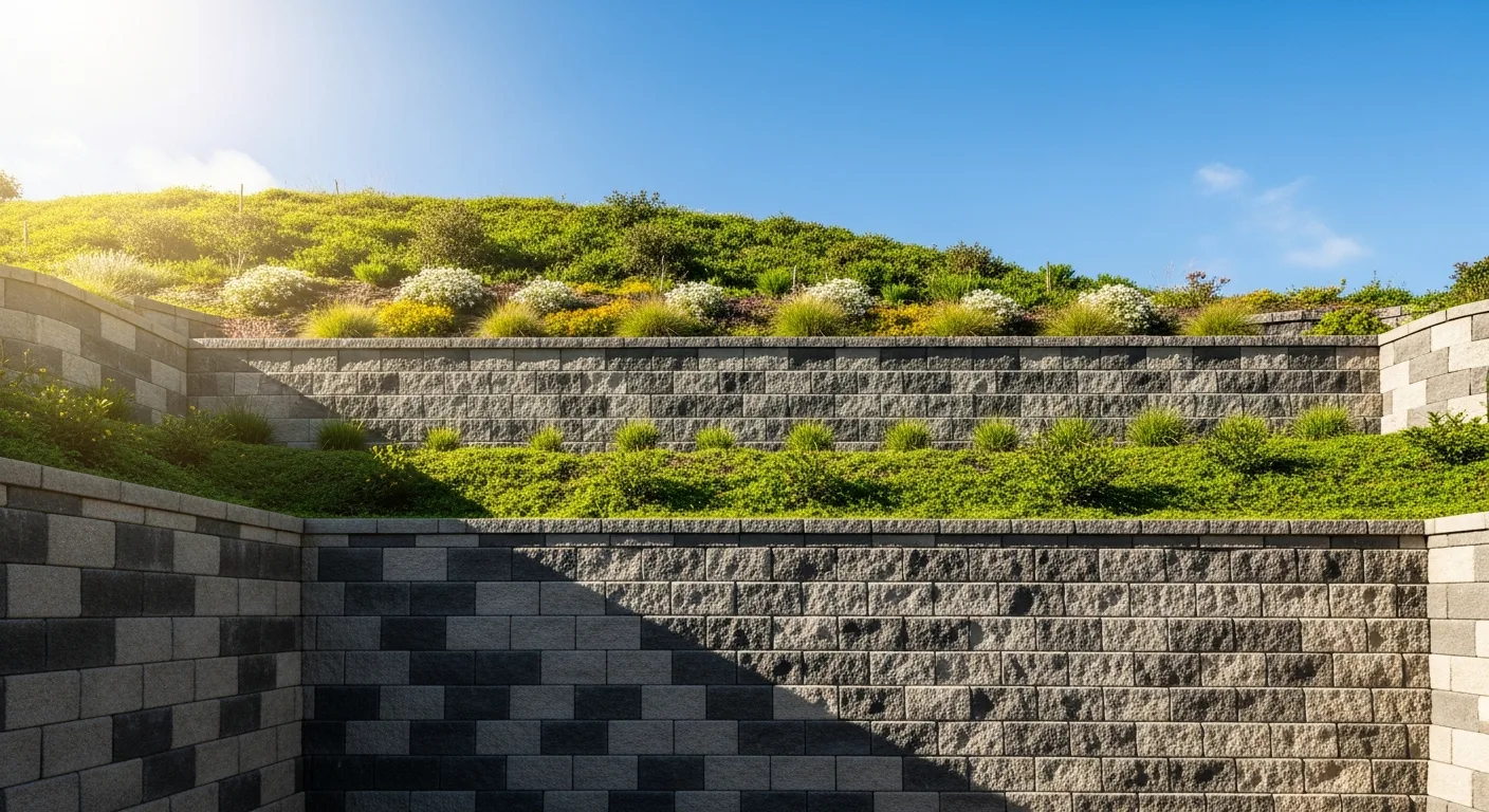
Retaining walls are everywhere in construction. Residential subdivisions, highway projects, commercial sites, and waterfront properties all use them to hold back soil and create usable grade changes. But not all retaining walls are the same, and picking the wrong type for a given situation leads to expensive failures.
This guide breaks down the five major retaining wall types, when to use each one, and the design considerations that keep them standing for decades. Whether you are a site contractor pricing a bid, a general contractor managing a project, or a project owner trying to understand what your engineer is specifying, this covers what you need to know.
Understanding Soil Pressure
Before jumping into wall types, you need to understand what a retaining wall actually does. The wall holds back a mass of soil that would otherwise slide or slump to its natural angle of repose. The soil pushes against the wall with lateral earth pressure, and the wall has to resist that force without sliding, overturning, or failing structurally.
Three types of earth pressure matter:
Active pressure is the minimum lateral pressure from soil that is allowed to move slightly away from the retained soil mass. This is the design case for most retaining walls.
Passive pressure is the resistance from soil in front of the wall toe (the buried portion). It helps resist sliding.
At-rest pressure applies when the wall cannot move at all, like a basement wall braced by floor framing. At-rest pressure is higher than active pressure.
The actual pressure values depend on soil type, moisture content, slope angle, and any surcharge loads (driveways, buildings, equipment) on top of the retained soil. This is why retaining wall design requires a geotechnical investigation for anything beyond simple, short gravity walls.
1. Gravity Retaining Walls
Gravity walls resist soil pressure through their own weight. They are massive, heavy structures that rely on sheer mass to stay in place. No reinforcement in the soil behind them, no structural steel, just weight.
Common Materials
- Segmental concrete block (SRW): Interlocking manufactured blocks, typically 40 to 80 pounds each. The most popular choice for residential and light commercial walls up to about 4 feet.
- Natural stone: Fieldstone, limestone, or granite stacked with or without mortar. Beautiful but labor-intensive.
- Mass concrete: Poured concrete walls that are thick enough to resist overturning by weight alone. Less common today because cantilever walls use less concrete for the same height.
- Gabion baskets: Wire mesh cages filled with rock. Good for erosion control and low walls in areas where a natural look is desired.
- Timber: Pressure-treated landscape timbers or railroad ties. Cheap and easy for short walls, but limited lifespan.
Design Considerations
Gravity walls work best for walls up to about 4 feet in exposed height for unreinforced designs. Taller gravity walls require much more mass, which gets expensive and takes up a lot of space.
The base width of a gravity wall is typically 50 to 70 percent of the wall height. A 4-foot-tall gravity wall might need a 2 to 3-foot-wide base. That footprint matters when you are working near property lines or existing structures.
Key design checks:
- Overturning: The wall must not tip over. The resisting moment from the wall’s weight must exceed the overturning moment from soil pressure by a factor of safety of at least 1.5 (typically 2.0).
- Sliding: The wall must not slide forward. Friction between the base and the foundation soil must resist the horizontal force with a factor of safety of at least 1.5.
- Bearing capacity: The foundation soil must support the wall weight without excessive settlement.
For segmental block walls, the manufacturers provide design charts and engineering support. Walls over 4 feet typically require geogrid reinforcement in the backfill, which technically makes them MSE walls (covered below), not pure gravity walls.
Drainage
Every gravity wall needs drainage. At minimum:
- 12 inches of clean, free-draining gravel behind the wall
- Perforated drain pipe at the base, sloped to daylight or a catch basin
- Filter fabric between the gravel and native soil to prevent fines from clogging the drain
- Weep holes through the face of mortared stone or concrete gravity walls
Skip the drainage and you will be rebuilding the wall within a few years. Hydrostatic pressure from trapped water is the number one killer of retaining walls.
2. Cantilever Retaining Walls
Cantilever walls are reinforced concrete structures shaped like an inverted T or L. The vertical stem connects to a horizontal base slab (footing) that extends back under the retained soil. The weight of soil sitting on the heel of the footing is what resists overturning.
How They Work
The stem acts as a vertical cantilever beam, fixed at the base. The footing has a toe (extending in front of the wall) and a heel (extending behind, under the retained soil). Reinforcing steel in the stem resists bending from soil pressure, and the soil weight on the heel provides the stabilizing force.
This design is much more efficient than a gravity wall for heights over 4 feet because the soil itself provides most of the stabilizing weight. The wall uses far less concrete than a solid gravity wall of the same height.
When to Use Cantilever Walls
- Wall heights from 4 to 25 feet (beyond 25 feet, other methods become more practical)
- Permanent walls with long design life requirements
- Highway and infrastructure projects
- Commercial site work with significant grade changes
- Anywhere a gravity wall would be too large for the available space
Design Considerations
Cantilever wall design is strictly engineering work. The engineer must determine:
- Stem thickness and reinforcement (varies with height)
- Footing dimensions (heel length, toe length, total width, thickness)
- Steel reinforcement layout in both stem and footing
- Shear capacity at the stem-footing junction
- Settlement and bearing capacity
Typical proportions:
- Footing width: 50 to 70 percent of wall height
- Stem thickness at base: 8 to 12 percent of wall height
- Footing thickness: 7 to 10 percent of wall height
- Heel extension: roughly 60 percent of footing width
These are starting points. Actual dimensions depend on soil conditions, surcharge loads, and seismic requirements.
Construction Sequence
- Excavate to footing elevation
- Compact and proof-roll the subgrade
- Place mud slab or gravel base
- Set footing reinforcement and pour footing
- Set stem reinforcement with dowels from footing
- Form and pour stem (may require multiple lifts for tall walls)
- Strip forms and waterproof the back face
- Install drainage system
- Backfill in lifts with compaction
The backfill operation is critical. Compacting backfill in lifts of 8 to 12 inches prevents settlement behind the wall. Using heavy equipment too close to the wall during backfill can overload the stem before the backfill provides its stabilizing weight.
3. Mechanically Stabilized Earth (MSE) Walls
MSE walls are the workhorse of modern retaining wall construction, especially for highway and commercial projects. They combine a facing system with horizontal soil reinforcement (geogrid or metal strips) to create a reinforced soil mass that acts as a gravity structure.
How MSE Walls Work
The facing (usually precast concrete panels or segmental blocks) holds back the soil at the face. Behind the facing, horizontal layers of geogrid or steel reinforcement extend back into the backfill. The reinforcement bonds with the compacted backfill through friction, creating a large reinforced soil block that resists sliding and overturning like a massive gravity wall.
The reinforced zone typically extends back from the face at least 70 percent of the wall height, or a minimum of 8 feet. This means an MSE wall needs a significant footprint behind the face.
Facing Options
- Precast concrete panels: 5-foot by 5-foot or 5-foot by 10-foot panels with a textured face. The standard for highway and DOT work.
- Segmental concrete blocks (SRW): Same blocks used for gravity walls, but with geogrid between courses. Popular for commercial and residential projects.
- Wire mesh (welded wire face): Cheaper and faster to install. Often used for temporary walls or walls that will be vegetated.
- Modular concrete blocks: Larger blocks with integrated connection points for geogrid.
When to Use MSE Walls
- Walls from 4 feet to over 80 feet tall
- Highway projects (DOTs love MSE walls)
- Bridge abutments
- Anywhere you have room for the reinforced zone behind the face
- Sites with poor foundation soils (MSE walls are more tolerant of settlement than cantilever walls)
Design Considerations
MSE wall design involves both external stability (the whole reinforced mass as a gravity block) and internal stability (each layer of reinforcement must resist pullout and rupture).
External checks:
- Overturning (factor of safety 2.0 or more)
- Sliding (factor of safety 1.5 or more)
- Bearing capacity
- Global stability (deep-seated slope failure)
Internal checks:
- Reinforcement tensile strength at each layer
- Pullout resistance (reinforcement must extend far enough into the backfill)
- Connection strength between reinforcement and facing
MSE walls require select backfill material, typically a well-graded granular fill with specific gradation, plasticity, and compaction requirements. You cannot just push native clay soil back against the reinforcement and expect it to perform. The select backfill is one of the larger cost items on an MSE wall project.
Why MSE Walls Are So Popular
They are fast to build compared to cast-in-place concrete walls. No formwork, no curing time, no rebar tying. The facing units go up quickly, and the backfill operation is straightforward with the right equipment. For highway projects where speed matters and traffic impact must be minimized, MSE walls are hard to beat.
They also handle settlement better than rigid concrete walls. The facing panels have flexible joints that accommodate some differential movement without cracking.
4. Sheet Pile Walls
Sheet pile walls use interlocking steel, vinyl, or wood planks driven vertically into the ground. They are common in waterfront construction, deep excavations, and flood control, anywhere you need to hold back soil or water in a tight space.
Types of Sheet Piling
- Steel sheet piles: Z-sections, U-sections, or flat sections that interlock at the edges. The standard for structural applications. Driven with vibratory or impact hammers.
- Vinyl (PVC) sheet piles: Lighter, corrosion-resistant, but lower structural capacity. Used for bulkheads, seawalls, and light-duty applications.
- Timber sheet piles: Traditional wood planks, tongued and grooved. Limited to short walls and temporary construction.
- Concrete sheet piles: Precast concrete planks for permanent waterfront structures. Heavy and require crane installation.
When to Use Sheet Pile Walls
- Waterfront bulkheads and seawalls
- Cofferdams for bridge pier construction
- Deep excavation support (temporary or permanent)
- Flood walls and levees
- Sites with very limited space (no room for MSE reinforced zone or cantilever footing)
Design Types
Cantilever sheet pile walls rely on embedment depth alone for stability. The sheet pile extends below the excavation level, and passive soil pressure on the embedded portion resists the active pressure above. Limited to about 15 feet of exposed height depending on soil conditions.
Anchored sheet pile walls add tie-back anchors or deadman anchors near the top of the wall. The anchor provides additional lateral support, allowing taller walls or walls in weaker soils. Anchor design is a significant part of the engineering.
Design Considerations
- Embedment depth: Typically 1.0 to 1.5 times the exposed height for cantilever sheet piles, less with anchors
- Section modulus: The sheet pile section must resist bending moments from soil and water pressure
- Corrosion: Steel sheet piles in marine environments corrode over time. Design includes a corrosion allowance or protective coating. Sacrificial anodes or cathodic protection extend service life.
- Interlock integrity: The interlocking joints between sheet piles must maintain water-tightness if the wall also serves as a water barrier
- Driving conditions: Hard soils, cobbles, or boulders can make sheet pile driving difficult or impossible. Pre-drilling or jetting may be needed.
Installation
Sheet piles are driven with vibratory hammers (faster, less noise, better for interlocks) or impact hammers (better penetration in hard soils). A template or guide frame keeps the piles aligned and plumb during driving.
For waterfront work, the installation sequence often involves driving piles from a barge, which adds marine equipment costs and tide/weather scheduling constraints.
5. Soldier Pile and Lagging Walls
Soldier pile walls use vertical steel beams (the “soldiers”) set in drilled holes at regular spacing, with horizontal lagging (timber, concrete, or steel) spanning between them to hold back the soil. They are the standard method for supporting deep excavations in urban construction.
How They Work
The soldier piles are installed first, before any excavation begins. They are typically wide-flange steel beams (W shapes) set in drilled holes and backfilled with concrete or lean mix. The piles extend well below the planned excavation depth for embedment.
As excavation proceeds in lifts, horizontal lagging boards are placed between the pile flanges to retain the soil. The lagging can be timber planks, precast concrete panels, or shotcrete applied to the exposed soil face.
For deeper excavations, tie-back anchors are drilled through the soldier piles into the retained soil at one or more levels. These anchors are post-tensioned to pre-load the wall system before the next excavation lift begins.
When to Use Soldier Pile Walls
- Temporary excavation support for building foundations
- Permanent below-grade walls (with concrete facing)
- Urban sites where adjacent buildings and utilities must be protected
- Sites where vibration from sheet pile driving is not acceptable
- Mixed soil conditions where sheet piles cannot be driven
Design Considerations
- Pile spacing: Typically 6 to 10 feet on center. Closer spacing for weaker soils or higher walls.
- Pile section: W8, W10, W12, or W14 wide-flange beams depending on loads and spans
- Embedment depth: Must provide adequate passive resistance below excavation level
- Lagging design: Timber lagging is common for temporary walls. Size depends on soil pressure and span between piles.
- Anchor design: Number of anchor levels, anchor capacity, bond length in soil or rock, pre-stress load
- Deflection limits: Adjacent buildings may have strict deflection limits. Monitoring with inclinometers and survey points is standard practice.
Construction Sequence
- Drill holes for soldier piles (typically 24 to 36 inches diameter)
- Set soldier piles plumb and backfill holes with concrete or lean mix
- Excavate first lift (typically 4 to 6 feet)
- Install lagging between piles
- Drill and install first level of tie-back anchors (if required)
- Test and lock-off anchors to design load
- Repeat excavation, lagging, and anchor installation for each level
- Pour permanent concrete wall against lagging (if permanent wall is required)
This top-down construction sequence is critical. You must install lagging and anchors before excavating the next lift. Excavating too far ahead of the support system risks soil collapse and is a serious safety violation.
Choosing the Right Wall Type
Picking the right retaining wall type comes down to a few key factors:
Height: Short walls (under 4 feet) are usually gravity walls. Medium walls (4 to 15 feet) can be cantilever, MSE, or anchored sheet pile. Tall walls (over 15 feet) favor MSE or anchored systems.
Space available: MSE walls need the most space behind the face. Cantilever walls need moderate space for the footing. Sheet pile and soldier pile walls need the least space.
Soil conditions: Good granular soil supports almost any wall type. Poor soils (soft clay, high water table) may rule out certain options or require ground improvement.
Permanent vs. temporary: Temporary excavation support almost always uses soldier pile or sheet pile systems. Permanent walls offer more choices.
Budget: Gravity walls are cheapest for short heights. MSE walls are cost-effective for medium to tall heights. Cantilever walls cost more than MSE for the same height. Sheet pile and soldier pile costs depend heavily on site conditions.
Aesthetics: If the wall face will be visible, segmental block (gravity or MSE) and natural stone provide the best appearance. Precast concrete panels can be textured. Sheet pile and soldier pile walls are typically hidden or faced with a veneer.
Managing Retaining Wall Projects
Retaining wall projects involve coordination between geotechnical engineers, structural engineers, site contractors, and material suppliers. Submittals for reinforcement, backfill material testing, compaction reports, anchor testing, and survey monitoring all need tracking.
Projul’s project management features help you keep all of this organized in one place. From bid day through final inspection, having a central system for documents, schedules, and communication keeps retaining wall projects running smoothly. See how it works with a quick walkthrough.
Final Thoughts
Every retaining wall project is different. Soil conditions, space constraints, budget, and performance requirements all influence the right choice. The key is matching the wall type to the situation rather than defaulting to whatever you built last time.
Get a geotech report. Work with a qualified engineer for anything over 4 feet. And build it right the first time, because retaining wall failures are expensive, dangerous, and bad for your reputation.
Good contractors know their wall types, understand the soil they are building in, and follow the engineering. That combination, along with solid project management and scheduling, is what separates crews that build walls that last from crews that get called back to fix them.
Frequently Asked Questions
What is the most common type of retaining wall?
How tall can a retaining wall be without an engineer?
What is the cheapest type of retaining wall to build?
How deep should a retaining wall footing be?
Do retaining walls need drainage?
How long do retaining walls last?
What causes retaining walls to fail?
Can you build a retaining wall on a slope?
Related Articles

BIM Clash Detection: How to Catch Conflicts Before They Cost You on the Jobsite
BIM Clash Detection: How to Catch Conflicts Before They Cost You on the Jobsite Every contractor has a story about the...
Read More →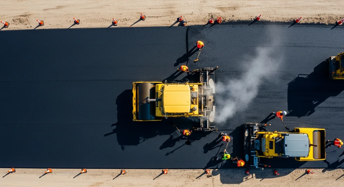
Asphalt Paving and Compaction Guide: Mix Types, Laydown Temperatures, and Quality Testing
Asphalt paving looks straightforward from a distance. A truck dumps material, the paver lays it down, and rollers...
Read More →
Construction Jobsite Wi-Fi & Connectivity Guide: Setting Up Reliable Internet in the Field
A practical guide to getting reliable internet on construction job sites. Learn about cellular hotspots, mesh networks,...
Read More →