Steel Erection Safety: OSHA Subpart R Guide
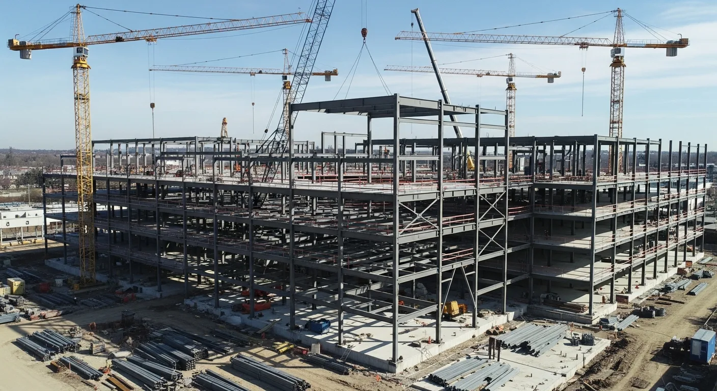
Structural steel erection is some of the most dangerous work in construction. You are lifting multi-ton beams and columns with cranes, connecting them at height, and building a structure that has to support itself at every stage of the process. The margin for error is slim, and the consequences of mistakes range from structural failure to fatal falls.
This guide covers the key aspects of steel erection that every ironworker, general contractor, and project manager needs to understand: connection types, column plumbing, OSHA 1926 Subpart R requirements, and fall protection systems. Whether you are running the iron crew or managing the overall project, this information keeps people safe and the job on track.
Structural Steel Connection Types
How steel members connect determines the strength, stability, and constructability of the structure. The structural engineer designs the connections, but the erection crew has to install them correctly in the field, often 50 or 100 feet in the air.
Bolted Connections
Bolted connections are the standard for field assembly. They are faster to install than welds, do not require hot work at height, and can be inspected visually and with calibrated wrenches.
High-strength bolts are the workhorses of steel connections. The two common grades are:
- ASTM A325: 120 ksi minimum tensile strength. Used for most structural connections.
- ASTM A490: 150 ksi minimum tensile strength. Used where higher capacity is needed. More brittle than A325 and cannot be reused after being fully tensioned.
Connection categories:
Bearing-type connections resist loads through shear across the bolt shank and bearing of the bolt against the hole wall. The bolts need to be snug-tight (the tightness achieved by a few impacts of an impact wrench or the full effort of a worker with a spud wrench). Simpler and faster to install.
Slip-critical connections rely on clamping force between the connected plates to resist loads through friction. The bolts must be fully tensioned to a specified minimum tension. Used where slip would be a problem: connections subject to fatigue loading, vibration, or where bolt slip would cause misalignment.
Bolt tensioning methods:
- Turn-of-nut method: Snug the bolt, then turn the nut a specified additional rotation (typically 1/3 to 1 full turn depending on bolt length and angle of surfaces). Reliable and does not require special equipment.
- Calibrated wrench method: Use a torque wrench calibrated daily with a Skidmore-Wilhelm bolt tension calibrator or equivalent. Apply the specified torque.
- Twist-off (TC) bolts: These have a splined end that shears off at the correct tension. The installation tool grips both the nut and the splined tip, tightening until the tip snaps off. Simple quality control since a missing tip means the bolt reached minimum tension.
- Direct tension indicators (DTI): Washers with raised bumps that flatten when the bolt reaches the target tension. A feeler gauge checks the remaining gap to verify tension.
Welded Connections
Field welding is used when bolted connections cannot provide the required strength or stiffness, or when the engineer specifies a moment connection (rigid frame) that must transfer bending forces.
Common field weld types:
- Complete joint penetration (CJP) groove welds: The weld fills the entire joint between members. Provides full-strength connections. Requires backing bars, proper joint preparation, and qualified welders.
- Partial joint penetration (PJP) groove welds: The weld fills only part of the joint depth. Less costly than CJP but lower capacity.
- Fillet welds: Triangular welds at the junction of two surfaces meeting at an angle. The most common weld type in structural steel. Easier to make than groove welds and require less joint preparation.
Field welding considerations:
- Welders must be qualified per AWS D1.1 (Structural Welding Code, Steel) for the specific positions and processes they will perform
- Welding procedures (WPS) must be documented and followed
- Weather protection is required when welding in rain, snow, or high wind
- Preheat requirements apply to thicker members and certain steel grades
- Weld inspection (visual, ultrasonic, magnetic particle, or radiographic) must be performed per the project specifications
Riveted Connections
Rivets are a legacy connection method. You will encounter them in renovation and retrofit work on older buildings and bridges, but new construction uses bolts and welds exclusively. If you are working on a riveted structure, the engineer will specify whether to replace rivets with high-strength bolts (common) or match the existing rivets.
Column Erection and Plumbing
Getting columns plumb and properly anchored is the foundation of the entire steel structure. If the columns are off, everything above them is off, and the problems multiply as you go up.
Anchor Bolt Installation
Anchor bolts are set in the concrete foundation before the steel arrives. Their placement must be precise because the steel is fabricated to exact dimensions, and anchor bolt misalignment causes major problems during erection.
Tolerances per AISC Code of Standard Practice:
- Anchor bolt center: within 1/8 inch of the plan location
- Anchor bolt group center: within 1/4 inch of plan
- Bolt projection above concrete: within minus 0 to plus 1 inch of specified height
Setting anchor bolts:
- Use a template (usually plywood or steel plate matching the base plate hole pattern) to position bolts before the concrete pour
- Secure the template and bolts against movement during the pour
- Protect bolt threads from concrete contact with tape or sleeves
- Survey bolt locations after the pour and before steel delivery to catch problems early
Column Base Plates
The base plate transfers column loads to the concrete foundation. The space between the base plate and the concrete must be filled to provide uniform bearing.
Leveling methods:
- Leveling nuts: Anchor bolts extend through the base plate, and nuts below the plate are adjusted to set the plate at the correct elevation. Grout is placed after the column is erected and plumbed.
- Shim stacks: Steel shims are placed on the concrete and shimmed to the correct elevation. The base plate sits on the shims, and grout fills the remaining space.
- Leveling screws: Screws welded to the base plate bear on the concrete and are adjusted for elevation. Common on heavy base plates.
Plumbing Columns
After a column is set on its base plate and the initial anchor bolt nuts are tightened, the erection crew plumbs the column using:
- Guy wires and turnbuckles: Cables attached to the column at height and anchored to the foundation or adjacent structure. Turnbuckles adjust the cable length to push or pull the column into plumb.
- Push-pull jacks: Mechanical or hydraulic jacks that brace against the foundation and push or pull the column base. Used for heavy columns that resist adjustment by cable alone.
Checking plumb:
A transit or total station set up at a distance from the column sights the column in two perpendicular directions. The surveyor calls adjustments to the crew working the guy wires. Laser plumb instruments can also be used for interior columns.
AISC tolerances for column plumb are 1/500 of the column length, with a maximum of 1 inch for columns up to 45 feet. Exceeding this tolerance affects the structural capacity and must be addressed before proceeding with erection above that level.
Temporary Bracing and Stability
A steel structure under erection does not have the stability of the finished building. Floor decking, concrete slabs, bracing, and connections that provide final stability are not yet in place. Temporary bracing must maintain stability throughout the erection process.
Key stability requirements:
- Columns must have a minimum of four anchor bolts
- Diagonal bracing (cables, angles, or temporary members) must be installed as erection proceeds
- No more than two tiers of steel should be erected without permanent bracing or decking installed on the lower tier
- Connections must have the minimum number of bolts installed before releasing the crane (two bolts minimum per OSHA)
The site-specific erection plan identifies the bracing sequence and when temporary bracing can be removed as permanent bracing and decking are installed.
OSHA 1926 Subpart R: Steel Erection Safety
Subpart R is the OSHA standard dedicated to steel erection. It was significantly revised in 2001 to address the high fatality rate in the industry and remains the governing standard for steel erection safety. Knowing it is not optional; it is the law.
Scope and Application
Subpart R applies to the erection of structural steel in construction, including:
- Multi-story buildings
- Single-story metal buildings
- Pre-engineered metal buildings
- Steel communication and transmission towers (some provisions)
- Steel storage racks over one story
- Bridge steel (with some modifications)
It does not apply to electrical transmission towers (covered under Subpart V) or residential steel framing that is equivalent to wood framing.
Site Layout and Construction Sequence (1926.752)
Before erection begins, the controlling contractor must provide the steel erector with:
- A safe site for delivering and storing steel
- Adequate access roads for delivery trucks and cranes
- Identification of underground utilities and overhead power lines
- Concrete strength certification for anchor bolts and foundations (the concrete must meet the specified minimum strength before steel is erected on it)
That last point is critical. Erecting steel on concrete that has not reached design strength can cause anchor bolt pullout or foundation failure.
Hoisting and Rigging (1926.753)
All hoisting operations must be performed by qualified riggers and signal persons. Key requirements:
- Pre-shift visual inspection of cranes and rigging equipment
- Routes for suspended loads must be pre-planned to avoid working over employees
- No riding the load or the headache ball
- Tag lines to control loads during lifting
- Multiple-lift rigging (Christmas-treeing) is permitted under specific conditions with engineered rigging procedures
Structural Stability (1926.754)
This section covers column anchorage, beams and columns, and stability requirements during erection:
- Column anchorage: Four anchor bolts minimum per column. Anchor bolts must not be repaired, replaced, or field-modified without the approval of the structural engineer.
- Beam connections: Each beam must be secured with a minimum of two bolts at each connection before being released from the crane. Members must not be forced into place with drift pins or other means that distort the connection.
- Column splices: Perimeter columns must be spliced with enough bolts to resist a 300-pound eccentric load 18 inches from the column face (to resist the impact of a falling worker against the column).
Open Web Steel Joists (1926.757)
Steel joists are particularly hazardous because they are lightweight, relatively flexible, and prone to rolling or buckling before they are permanently braced. Subpart R has specific requirements:
- Joists must not be placed on supports unless the supporting structure is stabilized
- The erection bridging must be installed before the next joist is placed (for joists spanning 40 feet or less)
- For spans over 40 feet, a written joist erection plan from a qualified person is required
- No worker can walk on joists until all bridging is installed and anchored
Joist collapses during erection have killed multiple workers. Follow the bridging requirements exactly.
Fall Protection (1926.760)
Fall protection in steel erection differs from the general construction fall protection standard (Subpart M). The key differences:
General steel erection workers: Fall protection required at 15 feet (compared to 6 feet under Subpart M). Between 15 and 30 feet, workers can use conventional fall protection, safety nets, or positioning devices.
Connectors: Workers who connect steel members at height. Between 15 and 30 feet, connectors must have fall protection but are allowed to use a personal fall arrest system, a positioning device, or a safety net. They do not have to be continuously tied off while making the actual connection if they are on a secured walking/working surface.
Above 30 feet, connectors must be protected the same as all other workers.
Deckers: Workers installing metal decking. Fall protection required at 15 feet. Controlled Decking Zones (CDZ) are permitted as an alternative to conventional fall protection, but only under strict conditions:
- The CDZ cannot extend more than 90 feet from the leading edge
- The CDZ must be clearly marked
- Only decking and related work can occur in the CDZ
- Workers in the CDZ must be trained and experienced in decking operations
Falling Object Protection (1926.759)
Falling tools and materials from steel erection are a constant hazard to workers below. Subpart R requires:
- Secured storage for bolts, drift pins, and tools at height (bolt baskets, tool bags)
- Controlled access zones below overhead steel erection when nets or canopies are not feasible
- Perimeter protection (screens or nets) to prevent objects from falling off the structure’s edge
Fall Protection Systems for Steel Erection
Fall protection in steel erection requires equipment and systems designed for the specific conditions of working on an open steel frame.
Personal Fall Arrest Systems (PFAS)
A PFAS consists of a full-body harness, a lanyard or self-retracting lifeline (SRL), and an anchorage point rated for 5,000 pounds per attached worker (or designed by a qualified person with a safety factor of 2).
Harness requirements:
- Full-body harness is the only acceptable body support (no belts for fall arrest)
- D-ring location at center back between shoulder blades for fall arrest
- Side D-rings for positioning only, not fall arrest
- Inspect before each use for cuts, fraying, burns, and hardware damage
Lanyard and SRL selection:
- Shock-absorbing lanyards limit the arresting force on the body to 1,800 pounds or less. They deploy a tear-away section that extends the lanyard length during a fall. This means you need enough clearance below the anchorage for the total fall distance plus deceleration distance plus harness stretch.
- Self-retracting lifelines (SRLs) retract excess line like a seat belt. They lock quickly in a fall, limiting free-fall distance to about 2 feet. Better than shock-absorbing lanyards when working close to the anchorage point because they reduce total fall distance.
- Leading edge SRLs are specifically designed and rated for use where a fall could cause the lifeline to contact a sharp edge. Standard SRLs can be cut by a steel beam edge during a fall.
Horizontal Lifelines
Cable or rail systems strung between columns or along beams allow workers to move along the structure while remaining continuously tied off. Horizontal lifelines must be designed by a qualified person because the forces in the system during a fall can be very high (a cable anchored at both ends can generate forces 3 to 5 times the worker’s weight at the anchors).
Beam Clamps and Trolleys
Portable beam clamps attach to the top flange of a steel beam to create an anchorage point. Trolley-style clamps slide along the beam, allowing the worker to move. Both must be rated for the required capacity and properly sized for the beam flange width and thickness.
Safety Nets
Safety nets installed below the working level catch falling workers without requiring active use of personal equipment. They must be installed as close as practical below the work level, with a maximum drop of 30 feet. Nets must extend at least 8 feet beyond the edge of the work surface (for falls up to 5 feet) with greater extension for higher working surfaces.
Erection Sequence and Planning
Pre-Erection Planning
Before the first piece of steel goes up:
- Verify foundation and anchor bolt survey data. Compare as-built anchor bolt locations to the steel shop drawings. Identify conflicts now, not when the crane is hooked to the first column.
- Review the erection plan. The steel erector’s qualified person should prepare a written sequence that identifies the order of erection, crane positions, temporary bracing requirements, and stability checkpoints.
- Confirm crane capacity and positioning. The crane must be able to reach all pick points at the required capacity, accounting for the actual ground conditions and setup radius.
- Stage material. Steel should be staged in the order it will be erected, with bundles and tags accessible. Shaking out steel (spreading it on the ground for sorting) requires space and planning.
- Hold a pre-erection safety meeting with the crane operator, signal person, connectors, bolt-up crew, and all other personnel. Cover the erection sequence, communication signals, fall protection requirements, and emergency procedures.
Erection Sequence
A typical multi-story steel erection follows this general sequence:
- Set columns on anchor bolts, make initial connections
- Plumb and brace columns
- Set beams and girders between columns, install minimum bolts
- Install temporary bracing per the erection plan
- Install metal decking and weld or fasten to beams
- Complete bolt-up (install remaining bolts, tension slip-critical bolts)
- Final plumb and alignment survey
- Release temporary bracing as permanent bracing and connections are completed
- Repeat for the next tier
Never get ahead of the bracing and decking. Erecting the next tier of columns before the lower tier is adequately braced and decked is how steel frames collapse during erection.
Managing Steel Erection Projects
Steel erection projects have a lot of moving parts: fabrication shop schedules, delivery sequencing, crane rental, erection crew coordination, bolt-up crews, welding, inspection, and safety compliance. Miss a delivery window and the crane sits idle at $1,500 or more per day. Send the wrong pieces first and the erection sequence falls apart.
Projul helps general contractors and steel erectors manage the scheduling, deliveries, and crew coordination that keep erection projects moving. Track fabrication submittals, schedule crane days, assign bolt-up and welding crews, and document safety inspections in one platform. When the steel schedule drives the overall project timeline, which it usually does, having a system that keeps everyone aligned saves real money.
See how it works with a quick demo, or check the pricing to see if it fits your operation.
Common Steel Erection Hazards and Controls
Collapse during erection. Follow the erection plan, install bracing as you go, and never rush ahead of the stability sequence.
Falls from height. Enforce the 15-foot fall protection trigger. Provide adequate anchorage points. Train every worker on proper harness use and inspection.
Struck-by falling objects. Use bolt baskets, tool lanyards, and controlled access zones. Secure everything at height.
Crane incidents. Verify load charts for actual conditions. Use qualified operators and signal persons. Maintain safe distances from power lines (OSHA requires 20 feet from lines up to 350 kV).
Caught-between hazards. Keep hands and fingers clear of connections during placement. Use tag lines, not hands, to guide loads. Never position yourself between a load and a fixed object.
OSHA 1926 Subpart R: Detailed Compliance Requirements
Understanding Subpart R at a detailed level is what separates crews that pass inspections from crews that get cited. The standard contains specific, measurable requirements that inspectors check against, and ignorance is never an accepted defense.
Site-Specific Erection Plans (1926.752(e))
A site-specific erection plan is required when the structure being erected does not conform to the conditions listed in OSHA’s conventional erection stability guidelines. In practice, most complex steel structures require one. The plan must be developed by a qualified person and must address:
- The sequence of erection, including which bays and tiers are erected first
- The location and type of all temporary bracing and when it is installed and removed
- The method for maintaining structural stability at every stage of erection
- Crane placement and capacity for each pick
- Connection details and the minimum number of bolts required before releasing a member from the crane
- Fall protection and falling object protection specific to the project
The controlling contractor (usually the general contractor) and the steel erector must both have copies of the plan on site. OSHA inspectors will ask to see it, and they will compare what is written in the plan to what is actually happening in the field. Deviations from the plan are citable violations.
Concrete Strength Certification (1926.752(a))
Before any steel is erected on a concrete foundation, the controlling contractor must provide written notification to the steel erector that the concrete has reached sufficient strength to support the loads imposed during erection. This is not a suggestion. It is a mandatory written document that must be available on site.
The notification must be based on actual concrete test results (cylinder break tests), not on estimated curing time. Erecting steel on concrete that has not reached design strength has caused anchor bolt pullouts, foundation cracking, and column base failures. If you are the steel erector and you have not received the concrete strength certification, do not start erection.
Multiple Lift Rigging (1926.753(e))
Multiple lift rigging, also called Christmas-treeing, is the practice of attaching several steel members to the same crane hook and lifting them together. It is permitted under Subpart R but only under strict conditions:
- A qualified rigger must supervise the operation
- The total weight of all members plus rigging must not exceed 75 percent of the crane’s rated capacity for the radius and configuration
- No more than five members can be rigged in a single lift
- Each member must be rigged independently so that releasing one does not affect the others
- Only beams and similar members can be multi-lifted. Columns must always be lifted individually.
- Tag lines must be used to control each member during the lift
Multiple lift rigging saves significant crane time on repetitive bay framing, but the safety requirements exist because a rigging failure with multiple members in the air multiplies the consequences.
Training Requirements (1926.761)
Every worker involved in steel erection must receive training from a qualified person on the hazards of steel erection and the requirements of Subpart R. Connectors must receive additional training specific to their work, including fall protection procedures and the proper use of connection tools.
Training must be documented. Use daily logs to record who attended training, what topics were covered, and the date. OSHA inspectors check training records, and having them organized and accessible demonstrates a serious safety culture.
Connection Types and Bolting Standards in Detail
The quality of bolted connections is only as good as the installation and inspection process. Understanding the standards that govern bolting is essential for anyone managing or performing steel erection.
RCSC Specification for Structural Joints
The Research Council on Structural Connections (RCSC) publishes the specification that governs the installation and inspection of high-strength bolts in structural steel connections. This specification, along with AISC standards, defines what constitutes a properly installed bolt.
Snug-tight condition is the baseline. A bolt is snug-tight when all plies in the joint are in firm contact and the bolt has been tightened by the full effort of a worker with an ordinary spud wrench or by a few impacts of an impact wrench. For bearing-type connections, snug-tight is all that is required.
Pretensioned condition is required for slip-critical connections and certain other applications specified by the engineer. The bolt must be tensioned to the minimum value specified in the RCSC tables (for example, a 3/4-inch A325 bolt must reach 28 kips of tension). Achieving and verifying this tension is where the turn-of-nut, calibrated wrench, TC bolt, and DTI methods come into play.
Bolt Installation Sequence
In a connection with multiple bolts, the tightening sequence matters. Start with the bolts nearest the center of the connection and work outward. This prevents the outer bolts from locking the plates in a slightly misaligned position that creates gaps in the center. Progressive tightening in a pattern from the center outward draws the plies together uniformly.
For slip-critical connections, a second pass around all bolts is standard practice to verify that earlier bolts have not relaxed as adjacent bolts were tensioned.
Bolt Inspection
Inspection requirements depend on the connection type:
- Snug-tight bearing connections: Visual inspection to verify all bolts are present and appear tight. No tension verification required.
- Pretensioned connections: The inspector must verify the tensioning method was properly applied. For turn-of-nut, this means checking that the match marks show the correct rotation. For TC bolts, verify the splined ends sheared off. For DTI washers, check the gap with a feeler gauge.
- Slip-critical connections: Same as pretensioned, plus verification that the faying surfaces (contact surfaces) meet the specified surface condition (usually Class A or Class B slip coefficient).
Document every bolt inspection in your project records. Projul’s daily log feature lets your field team record inspection results, flag deficiencies, and attach photos of completed connections directly from the job site.
Crane and Rigging Operations for Structural Steel
Crane work is inseparable from steel erection. Every piece of steel that goes up does so at the end of a crane hook, and the interface between the crane operation and the erection crew is where many incidents occur.
Crane Selection and Capacity Planning
Selecting the right crane for a steel erection project requires matching the crane’s capacity to the heaviest pick at the greatest radius it will need to reach. The critical factors are:
- Maximum piece weight: The heaviest single member, including rigging weight and any spreader beams
- Maximum radius: The farthest horizontal distance from the crane’s center of rotation to the pick or set point
- Lift height: The hook height needed to clear the structure and set the member at its final elevation
- Ground conditions: The crane’s rated capacity assumes a firm, level surface. Soft ground, slopes, or proximity to excavations reduce the effective capacity
Crane operators work from load charts provided by the manufacturer. These charts show the maximum load at each radius for a given boom length and configuration. The operator must account for the actual conditions, including wind, rigging weight, and any dynamic effects from swinging or sudden stops.
Never exceed 75 percent of the crane’s rated capacity during steel erection unless the site-specific plan and a qualified person have approved the lift at a higher percentage. The standard industry practice is to keep routine picks at or below 75 percent to maintain a safety margin.
Rigging Hardware and Inspection
Every piece of rigging hardware used in steel erection must be inspected before each shift. This includes:
- Wire rope slings: Check for broken wires, kinks, crushing, corrosion, and end fitting damage. Remove from service if more than six randomly distributed broken wires in one rope lay, or three broken wires in one strand in one rope lay.
- Synthetic slings: Check for cuts, burns, melting, acid damage, and stitching failure. Synthetic slings must not be used in proximity to welding or torch cutting.
- Shackles: Check for deformation, cracks, worn pins, and legible load ratings. Never use a shackle with a bolt replacing the proper pin.
- Choker hitches: Reduce the rated capacity of slings. A single choker hitch reduces capacity to approximately 75 percent of the straight pull rating. Factor this into every lift plan.
Communication During Lifts
Clear communication between the crane operator, signal person, and connecting crew prevents incidents. Standard hand signals per OSHA 1926.1419 (or ASME B30.5) must be used unless voice communication (radio) is established.
Only one designated signal person directs the crane at any time. The stop signal, however, can be given by anyone who sees a hazard. This must be covered in the pre-erection meeting and reinforced daily.
Use your scheduling tools to coordinate crane days with erection sequences so the crane is positioned correctly for each phase and idle time is minimized. A well-coordinated crane schedule is the difference between a profitable steel job and one that bleeds money.
Advanced Fall Protection Systems for Ironworkers
Beyond the basic PFAS components covered earlier, several specialized fall protection systems address the unique challenges of working on an open steel frame.
Retractable Beam Straps
Retractable beam straps wrap around a steel beam or column and cinch tight, creating a temporary anchorage point rated for fall arrest. Unlike beam clamps that grip the flange, beam straps can be used on round columns, built-up sections, and members with obstructions on the flange. They are faster to deploy than cable systems and can be repositioned as the work progresses.
Cable Grab Systems
A cable grab (also called a rope grab or cable sleeve) attaches to a vertical or angled lifeline cable and travels freely as the worker moves. In a fall, the grab locks onto the cable and arrests the fall. These systems are common on columns where workers climb to make connections at the splice level. A vertical lifeline is attached to the column top and the cable grab rides the cable as the connector climbs.
Positioning Systems for Connectors
Connectors often need both hands free to align members and install bolts. Positioning systems use a body belt or positioning harness with side D-rings and a short adjustable lanyard that wraps around a column or beam. The worker leans back against the lanyard, which holds their position while keeping both hands free.
Positioning systems are not fall arrest systems. They limit the worker to a position where a fall is unlikely, but they must be backed up by a separate fall arrest system when working above 15 feet. Many connector harnesses integrate both positioning D-rings and a dorsal fall arrest D-ring.
Rescue Planning
Every fall protection plan must include a rescue procedure. A worker hanging in a harness after a fall arrest can develop suspension trauma (the harness compresses blood vessels in the legs, causing blood pooling and potentially fatal cardiovascular collapse) within 15 to 30 minutes. Rescue must be prompt.
The rescue plan should identify:
- Who is responsible for initiating rescue
- What equipment is available (aerial lift, ladder, rescue descent device, or trained rope rescue team)
- How the suspended worker will be reached and lowered
- Where emergency medical services will stage and how they will access the work area
Do not assume someone will figure it out when it happens. Write the plan, train the crew, and rehearse the rescue procedure before erection begins. Document rescue drills in your daily logs alongside your other safety records.
Final Thoughts
Steel erection is skilled, demanding, and dangerous work. The crews who do it well combine technical knowledge of connections and structural behavior with constant attention to safety. Subpart R exists because too many ironworkers were killed and injured before the industry developed these standards.
Know the rules. Follow the erection plan. Protect your crew from falls and falling objects. And manage the project with enough organization that the erection sequence, crane schedule, and material deliveries all line up when they are supposed to.
Good steel erection is about planning as much as it is about iron. The crews that plan well, communicate well, and stay disciplined about safety are the ones that go home safe and build structures that stand for decades.
Frequently Asked Questions
What is OSHA Subpart R for steel erection?
At what height is fall protection required during steel erection?
What are the main types of structural steel connections?
What does plumbing a steel column mean?
How many bolts are required for an initial connection during steel erection?
What is a steel erection site-specific erection plan?
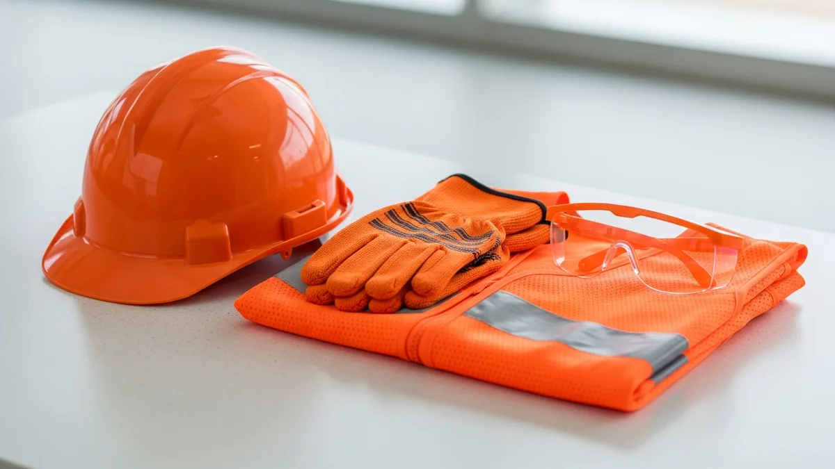
What PPE is required for structural steel erection?
Can steel erection continue in high winds?
Related Articles
Construction Crane Safety: Requirements, Inspections, and Best Practices
Crane operations are some of the highest-risk activities on any jobsite. This guide covers OSHA requirements,...
Read More →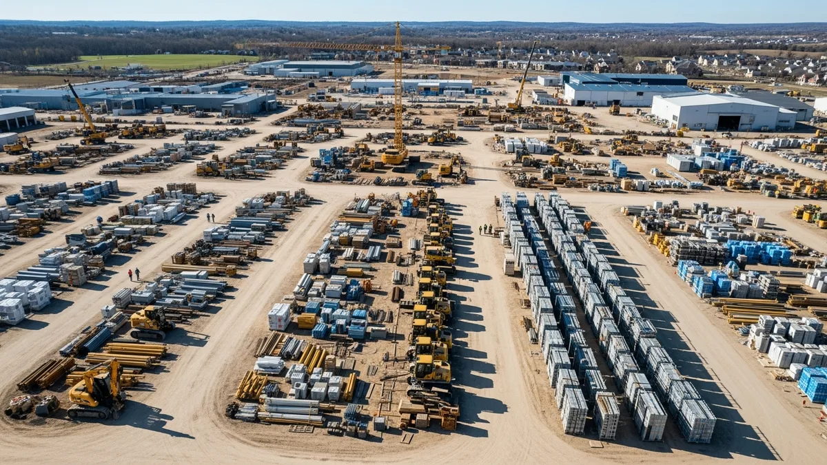
Construction Stormwater Management: Compliance and Best Practices
Stormwater violations can shut down a jobsite and cost tens of thousands in fines. Most compliance failures come down...
Read More →
Construction Zoning and Land Use: What Contractors Need to Know
Zoning and land use rules catch contractors off guard more often than most people realize. This guide covers zoning...
Read More →