Temporary Shoring in Construction: Types, Safety, and Best Practices
Temporary Shoring and Bracing Guide for Construction Projects
Temporary shoring and bracing are the unsung heroes of construction. Nobody notices them when they are doing their job. But when they fail, people get hurt and structures collapse. Whether you are pouring a multi-story concrete frame, removing a load-bearing wall in a renovation, or stabilizing an excavation, understanding shoring and bracing principles is fundamental to safe construction.
This guide covers the types of temporary support systems you will encounter, how loads are calculated, the safety requirements you must follow, and the practical field knowledge that keeps your projects running safely.
Why Temporary Shoring Matters
Every structure goes through a vulnerable phase during construction. Concrete has not cured to design strength. Steel connections are not all bolted up. Masonry walls are not fully grouted. During these phases, temporary support systems carry the loads that the permanent structure cannot yet handle.
Getting shoring wrong has real consequences. Formwork collapses are among the most deadly construction accidents. When a multi-story concrete shoring system fails, the progressive collapse can bring down multiple floors in seconds, with almost no warning.
The good news is that shoring failures are almost always preventable. They typically result from inadequate design, overloading, improper installation, premature removal, or a combination of these factors. Understanding the principles in this guide helps you avoid all four.
Types of Temporary Shoring Systems
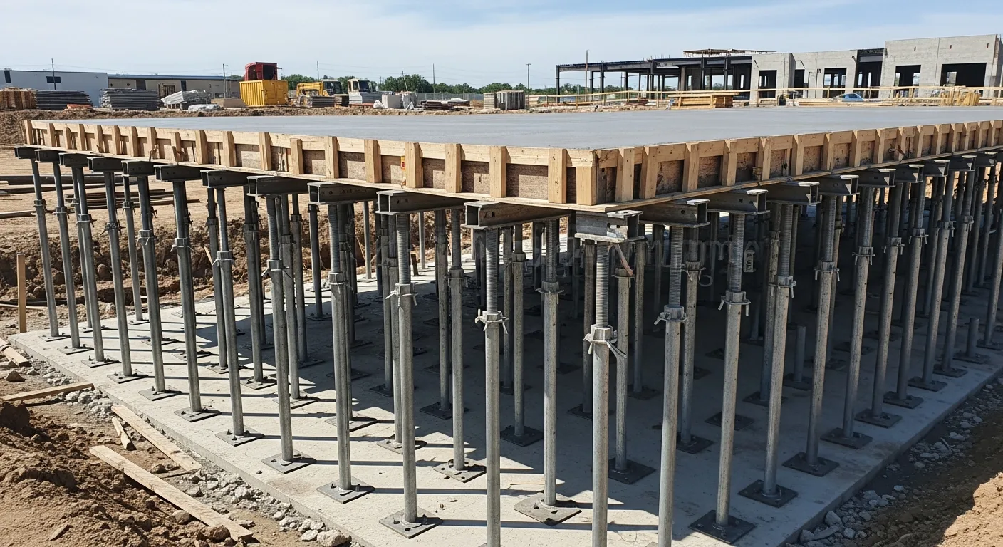
Adjustable Steel Shores (Post Shores)
The most common shoring element on concrete construction projects. These are telescoping steel tubes with a threaded adjustment mechanism that allows precise height setting. They come in light-duty, medium-duty, and heavy-duty ratings, typically ranging from 5,000 to 15,000 pounds of capacity per shore.
Best for: Slab-on-metal-deck shoring, residential concrete work, light commercial projects, and renovation work where you need to support a floor while modifying the structure below.
Key considerations: Always use the manufacturer’s load tables, which account for the shore length (capacity decreases as the shore gets taller). Never extend a shore beyond its rated maximum height. Make sure the base plate sits on a solid, level surface that can handle the concentrated load.
Shoring Frames (Heavy-Duty Frames)
These are modular steel frames, similar in appearance to scaffolding frames but engineered for vertical load support. They stack in tiers with cross-bracing and can support substantial loads when properly configured.
Best for: Multi-story concrete construction, heavy slab pours, post-tensioned slabs, and any application requiring high load capacity over a large area.
Key considerations: Frame shoring requires engineered layout drawings that specify the frame spacing, cross-bracing configuration, screw jack extensions, and base plate requirements. The capacity depends on the frame spacing, tier height, and bracing configuration. Do not assume that closer spacing always means more capacity; the bracing must be adequate to prevent buckling.
Timber Shoring
Before steel adjustable shores became common, timber posts and beams were the standard shoring method. Timber shoring is still used on smaller projects, renovation work, and in situations where steel shores are not available.
Best for: Small residential projects, temporary support during wall removal, emergency shoring of damaged structures.
Key considerations: Timber capacity depends on species, grade, cross section, and unbraced length. A standard 4x4 Douglas Fir post can support about 6,000 to 9,000 pounds depending on height, but check the NDS (National Design Specification for Wood Construction) tables for the specific conditions. Timber shores need solid bearing at top and bottom, wedges for height adjustment, and lateral bracing to prevent buckling.
Hydraulic Jacks and Needle Beams
For renovation work where you need to remove or modify a load-bearing wall, needle beams with hydraulic jacks are the standard approach. Steel beams (needle beams) are installed through the wall above the opening, supported on temporary posts or jacks on each side. The jacks allow precise load transfer and height adjustment.
Best for: Load-bearing wall removal, structural modification work, underpinning operations, and situations requiring controlled load transfer.
Key considerations: This work must be engineered. The needle beam size, jack capacity, post locations, and sequence of operations all need to be specified by a structural engineer. The temporary support must be in place and loaded before you start demolishing the existing structure.
Raking Shores (Inclined Shores)
Raking shores are inclined braces that support a wall laterally, preventing it from leaning or collapsing. They are common in historic preservation, emergency stabilization of damaged buildings, and masonry construction.
Best for: Stabilizing freestanding walls, supporting party walls during adjacent demolition, emergency shoring of damaged structures after storms or earthquakes.
Key considerations: The angle of the raking shore affects its capacity. The ideal angle is between 60 and 75 degrees from horizontal. The shore must have a solid footing that can resist both vertical and horizontal forces. A raking shore that kicks out at the base is useless and dangerous.
Flying Forms and Table Forms
On large commercial concrete projects, flying forms (or table forms) combine the formwork and shoring into a single unit that is moved as a complete assembly from one bay to the next using a crane. These systems are efficient for repetitive floor construction on projects with consistent floor-to-floor heights and column spacing.
Best for: Multi-story commercial buildings with repetitive floor plans, parking garages, and high-rise construction.
Key considerations: Flying form systems require significant upfront investment in engineering and fabrication. The cycle time savings on large projects justify the cost, but they are not practical for small projects or buildings with irregular layouts.
Engineered Shoring Systems (Proprietary)
Major formwork manufacturers like PERI, Doka, EFCO, and Ellis offer proprietary shoring systems that combine frames, towers, and decking into integrated packages. These systems come with manufacturer engineering support, load tables, and layout software. They cost more per day than generic frames or post shores, but the engineering support and faster installation often make up the difference on larger projects.
Best for: Large commercial and infrastructure projects, bridges, elevated highways, projects where the shoring heights or loads exceed what standard frame shoring can handle.
Key considerations: You are locked into that manufacturer’s ecosystem for the duration of the project. Mixing components from different manufacturers is never acceptable and often dangerous. The manufacturer’s field rep should be on site for initial setup and available for questions throughout the project.
Shoring System Cost and Use Case Comparison
Picking the right shoring system comes down to the load you need to carry, the height you need to reach, how long it stays in place, and what your budget looks like. Here is a practical comparison to help you decide.
| System Type | Typical Cost (Rental/Month) | Max Capacity Per Unit | Best Height Range | Setup Speed | Best Application |
|---|---|---|---|---|---|
| Adjustable Steel Post Shores | $5 to $10 each | 5,000 to 15,000 lbs | Up to 16 ft | Fast | Residential slabs, light commercial, renovations |
| Heavy-Duty Shoring Frames | $15 to $40 per frame | 10,000 to 30,000 lbs per leg | Up to 30 ft (stacked) | Moderate | Multi-story concrete, parking garages |
| Timber Posts (4x4 to 6x6) | $2 to $8 each (purchase) | 6,000 to 18,000 lbs | Up to 10 ft | Slow | Small reno work, emergency shoring |
| Hydraulic Jacks with Needle Beams | $25 to $75 per jack | 10 to 100 tons per jack | Varies | Slow | Load-bearing wall removal, underpinning |
| Raking Shores | $10 to $30 each | Varies by angle and size | N/A (lateral) | Moderate | Wall stabilization, historic preservation |
| Proprietary Engineered Systems | $50 to $200 per tower/day | 50,000+ lbs per tower | 60+ ft | Moderate | High-rise, bridges, heavy infrastructure |
| Flying/Table Forms | Project-specific pricing | Designed per application | Floor to floor | Fast (after setup) | Repetitive multi-story commercial |
A few things to keep in mind when comparing costs. The cheapest system per unit is not always the cheapest system for the job. Timber shoring looks cheap until you factor in the labor to cut, fit, wedge, and brace every post. Adjustable steel shores cost more to rent but go up in a fraction of the time. On a large multi-story project, the engineering support that comes with a proprietary system can save you weeks of schedule time and thousands in avoided mistakes.
Also factor in the logistics. Steel post shores fit in the back of a pickup truck. Heavy-duty frames need a flatbed. Proprietary tower systems need a crane for assembly. If your site has tight access, that limits your options regardless of what the load tables say.
Load Calculations for Temporary Shoring
If you are responsible for shoring design (or reviewing an engineer’s design), you need to understand where the numbers come from.
Dead Loads
Concrete weight: Normal weight concrete is about 150 pounds per cubic foot (pcf). For a slab pour, convert this to pounds per square foot by multiplying by the slab thickness in feet. An 8-inch slab: 150 pcf x 0.667 feet = 100 psf.
Formwork weight: Plywood decking, joists, stringers, and hardware typically add 5 to 15 psf depending on the system.
Reinforcing steel: Usually included in the concrete weight at the standard 150 pcf unit weight, but for heavily reinforced members, add a few psf.
Live Loads (Construction Loads)
ACI 347 (Guide to Formwork for Concrete) specifies minimum construction live loads:
- Minimum 50 psf for normal construction operations (workers, hand tools, small equipment)
- 75 psf minimum if motorized concrete buggies or similar equipment will be used on the formwork
- Point loads from concrete buckets, pump hose reactions, and other concentrated equipment must be accounted for separately
Impact and Dynamic Loads
Concrete placement creates impact forces, especially when using buckets or pump lines. ACI 347 does not specify a single impact factor but requires that the designer account for dynamic effects. A common approach is to apply a 25 percent increase to the static design loads during concrete placement.
Load Path Through Multi-Story Shoring
On multi-story construction, the shoring from the floor being poured transfers loads through the slab below, through its shoring, and down to the floors below that. The loads accumulate, and the lowest floor in the shoring system carries the highest total load.
This is why the shoring engineer needs to know the strength of each floor at each stage of construction. A slab that has only cured for three days cannot carry the same construction loads as a slab that has cured for 28 days.
Reshoring is the process of removing shores from a cured slab and immediately reinstalling new shores to redistribute the construction loads. This allows form stripping for reuse on the next floor while still providing multi-floor load distribution. The reshoring must be installed before any significant additional load is applied to the stripped floor.
Example Calculation
For a typical 8-inch normal weight concrete slab with conventional formwork:
| Load Component | Load (psf) |
|---|---|
| Concrete (150 pcf x 0.667 ft) | 100 |
| Formwork | 10 |
| Construction live load | 50 |
| Total | 160 |
With a safety factor, the design load for the shoring system would be approximately 160 to 200 psf. The shoring engineer divides this by the capacity of each shore to determine the required spacing.
Bracing Systems
While shoring handles vertical loads, bracing handles lateral loads and stability. Many construction failures involve inadequate bracing rather than shoring overload.
Formwork Bracing
Concrete formwork for walls and columns must resist the lateral pressure of wet concrete, which increases with pour height and pour rate. At the bottom of a wall form, the lateral pressure can exceed 1,000 psf for a fast pour. The bracing system (typically a combination of ties through the wall, walers, and external strongbacks or kickers) must resist this pressure without allowing the forms to bulge or blow out.
Tilt-Up Bracing
Tilt-up concrete panels need temporary bracing from the time they are tilted into position until the roof structure is installed and connected, providing permanent lateral support. Tilt-up braces are engineered steel tubes with adjustable end connections that bolt to inserts cast into the panel and to anchors in the floor slab.
Critical requirements:
- Braces must resist both inward and outward forces (wind can blow from either direction)
- Minimum of two braces per panel, positioned in the upper third of the panel height
- Brace anchors must be designed for the full uplift and shear forces
- Braces stay in place until the roof diaphragm is complete and all connections are made
Steel Erection Bracing
Structural steel frames need temporary bracing during erection until enough of the permanent bracing system is installed to provide stability. OSHA requires that the erector follow a steel erection plan that specifies the bracing sequence.
Column plumbing cables, temporary diagonal braces, and bolted connection tightening sequences are all part of the stability plan during steel erection.
Masonry Wall Bracing
Unreinforced masonry walls are extremely vulnerable to wind loads during construction before they are fully grouted and connected to the floor and roof structure. Temporary bracing must resist the wind pressure on the exposed wall area, which can be substantial on a tall wall with no roof to share the load.
The Mason Contractors Association of America (MCAA) publishes guidelines for temporary bracing of masonry walls during construction. The bracing must remain in place until the wall is fully grouted, the reinforcement is in place, and the floor or roof diaphragm is connected.
Safety Requirements and OSHA Standards
OSHA takes shoring and bracing seriously. The relevant standards include:
29 CFR 1926.703 (Concrete and Masonry Construction - Shoring) requires:
- Shoring designed by a qualified designer
- Shoring inspected by a competent person before concrete placement
- No workers permitted under freshly poured concrete until shoring is confirmed adequate
- Shoring not removed until the concrete has sufficient strength
29 CFR 1926.703(b) specifically addresses reshoring:
- Reshoring design must account for all loading conditions
- Reshoring must be placed as soon as original shores are removed
29 CFR 1926.756 (Steel Erection - Beams and Columns) addresses temporary bracing during steel erection, including requirements for column stability and connection security.
Competent Person Requirement
OSHA requires a “competent person” to inspect shoring and bracing before, during, and after concrete placement. A competent person, by OSHA’s definition, is someone who can identify existing and predictable hazards and has the authority to take corrective action. This is not just the project manager checking a box. It needs to be someone who understands the shoring system and can spot problems.
Common OSHA Violations Related to Shoring
- No engineered shoring plan
- Exceeding the rated capacity of shoring components
- Missing or inadequate cross-bracing on shoring frames
- Shores bearing on unstable surfaces (mud, unfrozen fill, unsupported slabs)
- Premature shore removal before concrete reaches required strength
- Workers under suspended loads during shoring operations
Practical Field Tips
Base Conditions
The best shoring system in the world is useless if the bases are sitting on mud. Every shore, every post, every frame leg needs to bear on a surface that can handle the concentrated load without settling. On grade, this usually means compacted fill with timber mud sills to spread the load. On elevated slabs, check that the slab below can handle the point loads from the shores above.
Eccentric Loading
Shores work best when loaded concentrically (straight down through the center). When loads are applied off-center, the shore sees bending in addition to compression, which significantly reduces its capacity. Keep shores plumb and directly under the supported load. Use U-heads and base plates that allow the supported beam to sit centered on the shore.
Temperature and Weather
Cold weather affects both the shoring schedule (concrete takes longer to gain strength, so shores stay in place longer) and the shoring components (steel shores can be slippery when icy, timber shores absorb moisture and may swell or shrink). Hot weather accelerates concrete strength gain but can also cause thermal expansion of steel shores.
Wind loads on bracing systems increase dramatically with height. Bracing designed for a two-story building may not be adequate for the same building at the six-story stage when more wall area is exposed to wind.
Documentation and Inspection
Maintain a shoring log that records:
- Date and time of shore installation
- Shore type, capacity, and configuration
- Inspection results before, during, and after concrete placement
- Concrete cylinder break results (to verify strength before shore removal)
- Date and time of shore removal or reshoring
This documentation is required by OSHA and protects you in the event of an incident. Using construction project management software like Projul makes it straightforward to attach inspection reports, photos, and test results to the project record where everyone on the team can access them.
Managing Shoring Costs on Your Projects
Shoring is typically a rental expense, and the rental clock runs for the entire duration the shores are in place. On a multi-story concrete project, you might have three or four floors of shoring and reshoring in place simultaneously. At $5 to $15 per shore per month (depending on the type), the costs add up quickly.
Tracking shoring rental costs, delivery and pickup dates, and shore inventory is a job management headache that the right software can simplify. Projul’s job costing features let you allocate shoring costs to specific floors and phases, so you know exactly where your money is going.
Planning the shoring and reshoring sequence to minimize the total number of shores on site (while maintaining safety) is one of the best ways to reduce costs on multi-story concrete work. This requires close coordination between the shoring engineer, the concrete foreman, and the project schedule.
When to Call an Engineer
Not every shoring situation requires a licensed engineer, but many do. Here are the situations where you definitely need engineering:
- Multi-story concrete construction
- Shoring loads exceeding 10,000 pounds per shore
- Shoring on elevated slabs (need to verify the slab can carry the shore loads)
- Shores taller than 12 feet (buckling becomes critical)
- Any shoring that supports occupied space below
- Load-bearing wall removal in existing structures
- Emergency shoring of damaged structures
- Any situation where a failure could cause serious injury or death
When in doubt, get the engineer involved. The cost of a shoring design is trivial compared to the cost of a shoring failure. If you need help organizing the engineering requirements and tracking design approvals, schedule a demo with Projul to see how contractors manage these workflows.
Shoring Design Calculations and Engineering Requirements
Understanding when a professional engineer (PE) stamp is required and what goes into a shoring design helps you plan your project timeline and budget. Too many contractors get caught off guard when a building official asks for stamped shoring drawings and they do not have them.
When You Need a PE Stamp
The short answer is more often than most contractors think. Here are the situations where virtually every jurisdiction requires engineered, stamped shoring plans:
- Multi-story concrete construction. Any building with two or more elevated slabs being constructed needs a shoring and reshoring plan stamped by a PE. This is not optional. ACI 347 and most building codes require it.
- Shoring loads over 10,000 pounds per point. Once you get into heavy loads, the consequences of failure are too severe for field judgment alone.
- Shores taller than their rated unbraced height. Manufacturers publish load tables based on specific unbraced lengths. If your floor-to-floor height puts you outside those tables, you need an engineer to design the bracing or specify a different system.
- Shoring on elevated slabs or roofs. The slab below the shores needs to be checked for the concentrated loads. This almost always requires engineering.
- Load-bearing wall removal. The temporary support sequence for removing a load-bearing wall in an existing building needs to be designed by a structural engineer, full stop.
- Public safety exposure. If the shoring supports anything over a public sidewalk, roadway, or occupied space, it needs engineering.
- Emergency shoring of damaged structures. After a fire, earthquake, vehicle impact, or other damage, the shoring design should be done by an engineer who can assess the remaining capacity of the damaged structure.
What the Engineer Needs From You
Shoring engineers cannot design in a vacuum. Before calling the engineer, gather this information:
- Structural drawings showing the members to be supported, their sizes, and the design loads.
- Floor-to-floor heights and the clear height available for shoring (accounting for formwork depth and any obstructions).
- Concrete mix design and anticipated strength gain curve. The engineer needs to know how fast the concrete will gain strength to determine when shores can be removed.
- Construction sequence. Which floors are being poured in what order, and what is the planned cycle time between floors.
- Site conditions. What are the shores bearing on? Grade-level soil conditions, slab thickness and reinforcement below, or steel framing.
- Equipment loads. Will concrete buggies, pump trucks, or other heavy equipment be operating on the formwork?
- Schedule constraints. If you need to strip forms in three days instead of seven, the engineer needs to know so they can design the reshoring accordingly.
Typical Engineering Deliverables
A complete shoring design package should include:
- Shoring layout plan showing shore locations, types, and spacing for each bay and each floor.
- Shore schedule listing each shore type with its required capacity and maximum extension.
- Reshoring plan if applicable, specifying when original shores are removed and reshores installed.
- Bracing details showing cross-bracing requirements for frame shoring and lateral bracing for freestanding shores.
- Base and head details showing bearing plate sizes, mud sill requirements, and U-head or screw jack configurations.
- Load calculations demonstrating that each component is within its allowable capacity.
- Inspection checklist for the competent person to use in the field.
- Shore removal criteria specifying the concrete strength required before shores can be removed, and the method for verifying that strength (usually cylinder breaks).
The Cost of Shoring Engineering
Shoring engineering typically runs between $2,000 and $15,000 depending on the project complexity. For a straightforward three-story concrete building, expect $3,000 to $5,000. For a complex high-rise or post-tensioned structure, the cost goes up. But compare that to the cost of a shoring collapse: destroyed formwork ($50,000 to $500,000), schedule delays (weeks to months), OSHA fines ($15,000+ per violation), injury claims (unlimited), and the hit to your reputation. The engineering is always worth it.
OSHA Shoring Requirements Contractors Miss
Most contractors know the basics of OSHA shoring requirements. But there are specific rules that catch experienced crews off guard, especially when excavation shoring and formwork shoring overlap on the same project.
The 5-Foot Excavation Depth Trigger
OSHA 29 CFR 1926 Subpart P requires protective systems for any excavation deeper than 5 feet, unless the excavation is made entirely in stable rock. That means at 5 feet and 1 inch, you need sloping, benching, shoring, or a trench shield. No exceptions.
The part contractors miss: the 5-foot measurement is taken from the bottom of the excavation to the nearest ground surface. If you have a trench that is 4 feet deep but you are piling the spoil right next to the edge, and that spoil pile is 2 feet high, an OSHA inspector can argue that the effective depth is 6 feet from the bottom of the trench to the top of the spoil pile. Keep spoil back at least 2 feet from the edge, which is already required by 1926.651(j)(2).
Soil Classification Is Not Optional
Before you choose a protective system for an excavation, you must classify the soil. OSHA defines three soil types (A, B, and C) plus stable rock, and each type has different allowable slopes and shoring requirements. Type C soil (the weakest, including granular soils and submerged soil) requires the most protection.
Here is what contractors miss: the soil must be classified by a competent person using at least one visual test and one manual test. Looking at the dirt and saying “it seems pretty solid” does not count. You need to document the test method and results. Common acceptable tests include the thumb penetration test, the pocket penetrometer, the dry strength test, and the plasticity (ribbon) test.
If you cannot definitively classify the soil, you must default to Type C and provide the maximum protection. Most inspectors will ask to see your soil classification documentation, and not having it is a citable violation.
Daily Inspections Before Every Shift
OSHA 1926.651(k)(1) requires that a competent person inspect excavations, adjacent areas, and protective systems before the start of work each day, after every rainstorm, and after any other hazard-increasing occurrence. This is not a suggestion. It is a daily requirement, and the inspection must happen before anyone enters the excavation.
The common mistake is treating this as a one-time inspection. You inspected Monday morning, so you are good for the week? Wrong. Rain Tuesday night means you inspect again Wednesday morning before anyone goes in. A heavy equipment vibration event adjacent to the trench means you inspect again.
Document every inspection with the date, time, inspector name, conditions observed, and any corrective actions taken. Construction management software makes this documentation automatic and keeps it tied to the specific project and location.
Access and Egress Requirements
Every excavation 4 feet or deeper must have a means of egress (ladder, ramp, or steps) that requires no more than 25 feet of lateral travel. Contractors frequently violate this on long trench runs where the ladder is at one end and the crew is working 50 or 100 feet away.
The Competent Person Actually Needs to Be Competent
OSHA defines a competent person as someone capable of identifying existing and predictable hazards in the surroundings or working conditions and who has authorization to take prompt corrective measures to eliminate them. This person needs to understand soil mechanics, shoring system limitations, and the specific hazards of the excavation.
Assigning the newest laborer on the crew as the competent person because nobody else wants the responsibility is a recipe for a citation and, worse, a potential fatality. Invest in proper training. OSHA does not require a specific certification, but training records that show the competent person understands excavation hazards are your best defense during an inspection.
Utilities and Adjacent Structures
Before excavating, you must determine the location of underground utilities (1926.651(b)). But contractors also miss the requirement to protect adjacent structures. If your excavation could undermine a sidewalk, road, foundation, or other structure, you must provide shoring or bracing to prevent collapse. This means shoring the excavation wall, underpinning the adjacent foundation, or both.
Shoring Removal Sequence and Safety Protocols
Taking shores out is just as dangerous as putting them in, maybe more so, because by the time you are stripping shores, the crew is often in a hurry to move on to the next phase. Rushing shore removal has caused some of the worst construction collapses on record.
Verify Concrete Strength Before Removing Anything
Never remove shores based on calendar days alone. The only reliable way to know if concrete can support itself is to test it. Break cylinder samples at a certified lab and compare the results to the required strength specified in the shoring plan. Most shoring engineers specify a minimum of 75 percent of the 28-day design strength before shores can be removed, though this varies by member type and span.
For slabs, the minimum is often 7 days at normal curing temperatures, but cold weather can push this to 14 days or more. For beams and girders with longer spans, expect 14 to 21 days minimum. Post-tensioned members have their own requirements tied to the stressing sequence.
If you do not have cylinder break data, the shores stay. Period. No exceptions. Document the cylinder break results and keep them in the project file.
The Correct Removal Sequence
Shoring removal follows a specific sequence to prevent overloading any single area:
- Start at the center of the span and work toward the supports. This is the opposite of what feels intuitive. You want the slab to gradually pick up its own load starting at the point of maximum deflection. If you strip the shores at the supports first, the full span is suddenly unsupported and the center sees the maximum bending moment with no help.
- Remove shores uniformly. Do not strip one bay completely while leaving adjacent bays fully shored. This creates an abrupt load transition that can overstress the slab at the boundary.
- Lower shores gradually. Use the screw jack to lower each shore about half an inch, then move to the next shore. Come back and lower another half inch. This gradual load transfer lets you watch for any signs of distress (cracking, excessive deflection, unusual sounds) before the slab takes the full load.
- Install reshores immediately if required. On multi-story work, the reshoring plan specifies which floors need reshores and when. The reshores must be snug (in contact with the slab above and the floor below) but not jacked tight enough to lift the slab. They are there to share the load, not to pre-load the structure.
Warning Signs During Shore Removal
Stop work immediately and get the engineer involved if you observe any of these during shore removal:
- Cracking in the slab or beam. Hairline shrinkage cracks are normal. Cracks that are opening up, running along the reinforcement, or appearing suddenly are not.
- Excessive deflection. Some deflection is expected as the slab takes its own weight, but if the deflection is visibly more than the engineer predicted, stop and measure it.
- Unusual sounds. Popping, cracking, or grinding noises during shore removal mean something is moving that should not be.
- Shores that are difficult to remove. If a shore is tightly loaded and does not want to come loose, that means it is carrying more load than expected. Do not force it. Find out why before proceeding.
- Water or staining on the concrete surface. This can indicate the concrete did not cure properly in that area and may not have reached the required strength.
Protecting the Crew During Removal
Shore removal creates a falling object hazard. Shores, braces, formwork panels, and hardware can fall during stripping operations. Enforce these protocols:
- Clear the area below. No one should be working directly under the area being stripped. Barricade the floor below if necessary.
- Wear hard hats and safety glasses. This is always required on a construction site, but it is especially critical during stripping operations when debris is falling.
- Lower materials, do not drop them. Shores, stringers, and plywood should be lowered to the floor or passed down, not thrown off the edge of the deck.
- Secure loose components. Cross-bracing, screw jacks, and base plates can roll or slide off the deck if not controlled during removal.
- Work in teams. Shore removal is not a one-person job. At least two workers should be in the area so they can help each other and watch for hazards.
Documenting the Removal
Record the following for every shore removal operation:
- Date and time of removal
- Concrete cylinder break results and the age of the concrete at the time of removal
- Name of the competent person who authorized the removal
- Any observations during removal (deflection, cracking, unusual conditions)
- Reshoring installation details if applicable
- Weather conditions (temperature matters for concrete strength gain)
This documentation is not just for OSHA. It protects you if there is ever a structural question down the road. If a crack shows up in a slab two years later and someone asks whether the shores were removed too early, your records prove otherwise.
Bottom Line
Temporary shoring and bracing keep your projects standing during the most vulnerable phases of construction. Respect the loads, follow the engineering, inspect the installations, and do not rush the schedule. Your crew’s safety and your company’s reputation depend on getting this right every single time.
Frequently Asked Questions
What is the difference between shoring and bracing in construction?
Who is responsible for designing temporary shoring on a construction project?
How do you calculate the load on temporary shoring for a concrete slab?
How long does shoring need to stay in place after pouring a concrete slab?
What are the OSHA requirements for temporary shoring?
What is reshoring and when is it required?
Can you use scaffolding as temporary shoring?
How do you shore an existing floor for a heavy equipment installation?
Related Articles

Concrete Tilt-Up Construction: A Contractor's Complete Field Guide
Tilt-up construction accounts for roughly 15 percent of all industrial and commercial buildings in North America. This...
Read More →
How to Implement Construction Software Without Losing Your Mind
Most construction software rollouts fail. Not because the software is bad, but because the rollout was rushed. Here are...
Read More →
How Selections Can Pay for Themselves in Three Easy Steps
Most contractors lose thousands each year on wrong material orders, slow client decisions, and missed upsell chances....
Read More →