Backfill Compaction Testing Methods Guide
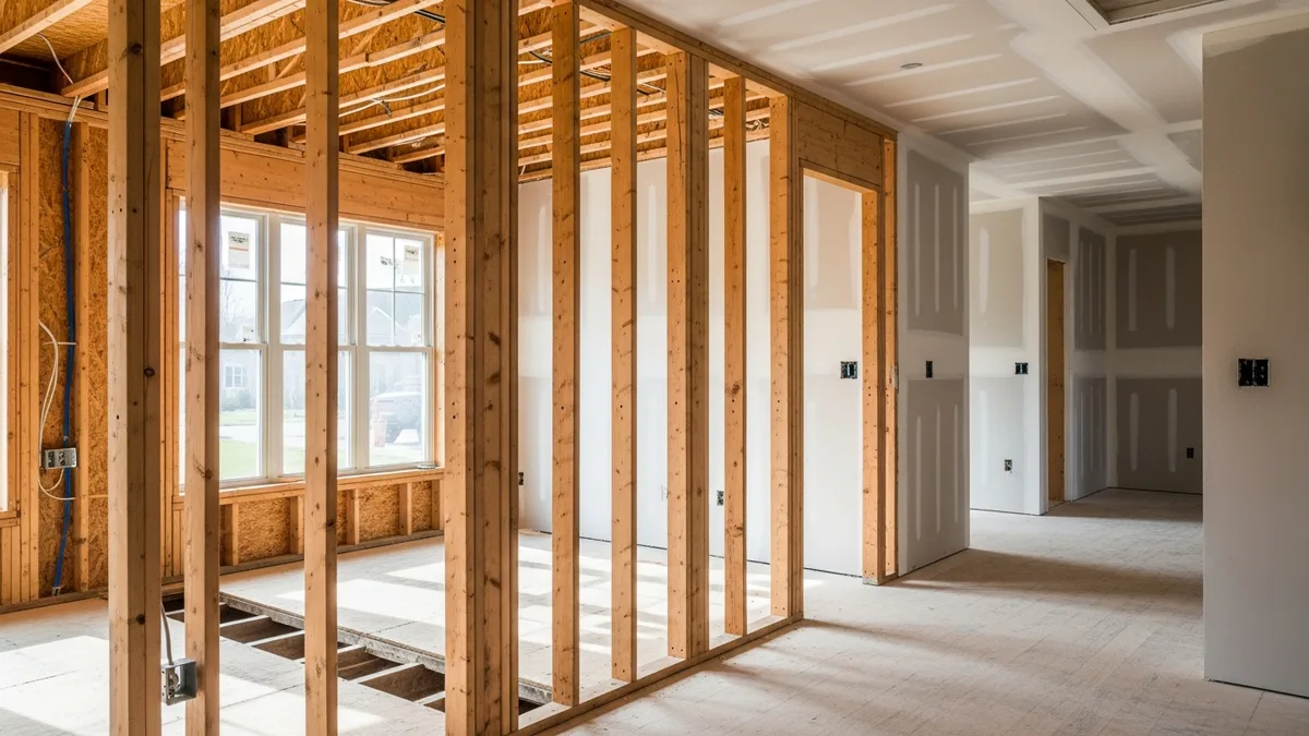
Backfill compaction is one of those tasks that does not get the respect it deserves until something goes wrong. A settled sidewalk, a cracked foundation wall, or a broken utility line buried three feet down can all trace back to backfill that was not compacted correctly. The frustrating part is that the fix is almost always more expensive than doing it right the first time.
Whether you are backfilling around foundations, in utility trenches, or across a graded site, compaction is the step that determines whether your work holds up for decades or starts failing within a year. This guide breaks down the testing methods, soil considerations, equipment choices, and quality control practices that contractors need to get backfill compaction right on every project.
Understanding Backfill Materials and Soil Types
Before you even fire up a compactor, you need to know what you are working with. Different soil types behave differently under compaction, and the material you choose for backfill directly affects how dense you can get it and how it will perform long-term.
Granular soils like sand and gravel are the easiest to compact and generally the most forgiving. They drain well, do not shrink or swell with moisture changes, and respond well to vibratory compaction. Most engineers prefer granular backfill around foundations and under slabs for exactly these reasons.
Cohesive soils like clay and silt are trickier. They are highly sensitive to moisture content, meaning they compact well only within a narrow moisture range. Too wet and the soil turns into a spongy mess that deforms under the roller. Too dry and the particles will not bind together no matter how many passes you make. If you are working with cohesive native soils as backfill, moisture conditioning becomes a non-negotiable part of your process.
Engineered fill or processed materials like crushed stone, recycled concrete aggregate, and select fill give you more predictable results. These materials have been screened, blended, or processed to meet specific gradation requirements, which means they compact consistently and hit target densities with less effort.
The Unified Soil Classification System (USCS) groups soils into categories based on grain size and plasticity. Knowing whether you are dealing with a well-graded gravel (GW), a silty sand (SM), or a high-plasticity clay (CH) tells you a lot about how the material will respond to compaction. Your geotech report should spell this out, and if it does not, get clarification before you start placing fill.
Understanding your soil ties directly into how you plan your earthwork and excavation operations. The material you dig out and the material you bring in both need a compaction plan.
Soil Classification for Backfill: The USCS System Explained
The Unified Soil Classification System (USCS) is the standard language engineers and contractors use to describe soil behavior. Every geotechnical report uses USCS symbols, and understanding them saves you from expensive mistakes when selecting and placing backfill material.
USCS divides soils into two broad categories: coarse-grained soils (more than 50% retained on the No. 200 sieve) and fine-grained soils (more than 50% passing the No. 200 sieve). Each category breaks down further based on gradation, plasticity, and organic content. The two-letter symbols tell you exactly what you are dealing with.
Coarse-Grained Soils: Your Best Backfill Options
GW (Well-Graded Gravel): This is the gold standard for structural backfill. A wide range of particle sizes means the smaller particles fill the voids between larger ones, creating a dense, stable mass with minimal effort. GW materials compact easily, drain freely, and resist frost heave. If you can specify your backfill material, this is what you want around foundations and under slabs.
GP (Poorly-Graded Gravel): Missing some particle sizes, so it does not pack as tightly as GW. Still a good backfill material but may require more compactive effort to hit target densities. Drainage is excellent because the uniform particle size creates large void spaces.
SW (Well-Graded Sand): Another excellent backfill choice. Compacts well with vibratory equipment, drains adequately, and provides good bearing support. SW is commonly used for utility trench backfill and general fill applications.
SP (Poorly-Graded Sand): Think beach sand or uniform dune sand. It compacts with vibration but can be prone to liquefaction in seismic zones and piping erosion when water flows through it. Acceptable for many backfill applications but watch for washout in areas with high water flow.
SM (Silty Sand): The silt fraction makes this material more moisture-sensitive than clean sands. It still compacts reasonably well but needs closer attention to moisture content. SM soils are common as native material on many job sites and work as backfill when properly moisture-conditioned.
SC (Clayey Sand): The clay content adds cohesion but also adds moisture sensitivity and shrink-swell potential. SC materials require more compactive effort than clean sands and a narrower moisture window. They work as backfill but demand more attention during placement.
Fine-Grained Soils: Proceed With Caution
CL (Low-Plasticity Clay): This is the most common clay encountered in construction. CL soils can serve as backfill when properly moisture-conditioned and compacted in thin lifts with sheepsfoot rollers. The key is staying within about 2% of optimum moisture content. Outside that window, you are wasting time and fuel.
CH (High-Plasticity Clay): Avoid using CH soils as structural backfill whenever possible. They shrink dramatically when dry, swell when wet, and have very low permeability. A CH backfill behind a retaining wall is a lawsuit waiting to happen because the swelling pressure can exceed the wall’s design capacity. If you must use CH material, the engineer needs to account for it in the design.
ML (Low-Plasticity Silt): Silts are the most frustrating soils in earthwork. They hold water but do not drain, they pump under rollers, and they are frost-susceptible. ML soils are marginal as backfill and require very careful moisture control and thin lifts. Many specs prohibit them outright for structural applications.
MH (High-Plasticity Silt): Even worse than ML. Extremely compressible, difficult to compact, and highly frost-susceptible. Do not use MH soils as backfill unless the engineer specifically approves it with modified specifications.
OL and OH (Organic Soils): Never use organic soils as backfill. Period. Organic material decomposes over time, causing progressive settlement that no amount of compaction can prevent. If your excavation turns up organic material, it gets hauled off site and replaced with engineered fill.
Pt (Peat): Completely unsuitable for any structural purpose. Remove and replace.
Practical Guidance: Matching USCS to Backfill Decisions
When you receive a geotechnical report, look for the USCS classification of both the native soils and any proposed import material. Here is a quick reference for backfill suitability:
- Excellent backfill: GW, GP, SW, GW-GM (well-graded gravel with silt)
- Good backfill: SP, SM, SC, GM (silty gravel)
- Acceptable with care: CL, GC (clayey gravel), ML (in non-structural applications)
- Poor backfill, avoid if possible: CH, MH
- Never use: OL, OH, Pt
If the spec calls for “select fill” or “structural backfill,” it almost always means a granular material in the GW, GP, SW, or SP range. Do not assume that any clean-looking dirt qualifies. Get it tested and classified before you place a single yard.
The Proctor Test and Establishing Compaction Standards
Every compaction specification references a target density, and that target comes from the Proctor test. This is the lab test that establishes the maximum dry density and optimum moisture content for a given soil. Without it, you are guessing at what “properly compacted” even means.
Standard Proctor (ASTM D698) uses a 5.5-pound hammer dropped from 12 inches. It simulates lighter compaction effort and is typically specified for general fill areas, landscaping, and non-structural backfill.
Modified Proctor (ASTM D1557) uses a 10-pound hammer dropped from 18 inches, delivering about 4.5 times more energy than the standard test. This is the benchmark for structural backfill, building pads, road subgrades, and anything that will carry significant loads.
The test produces a moisture-density curve that looks like an upside-down U. The peak of that curve is the maximum dry density at the optimum moisture content. When the spec says “95% compaction,” it means 95% of that peak density value.
Here is why this matters on the job: if your soil’s optimum moisture content is 12% and you are trying to compact at 8% or 18%, you will never hit your target density no matter how many passes you make. The lab results tell you exactly where you need to be, and your field crew needs to understand that number.
Get your Proctor tests done early. Waiting for lab results while your crew sits idle burns money fast. If you are importing fill material, get samples tested before the first truck arrives on site. Surprises with backfill material are expensive surprises.
Field Testing Methods for Compaction Verification
Once you start placing and compacting backfill, you need a way to verify that your work meets the specification. Several field testing methods exist, each with its own strengths and limitations.
Nuclear Density Gauge (ASTM D6938)
This is the workhorse of compaction testing. A nuclear density gauge uses a small radioactive source to measure both the wet density and moisture content of compacted soil in about 60 seconds. The device sits on the surface and sends gamma rays into the soil, then measures how many bounce back.
Advantages: Fast results, non-destructive, measures both density and moisture simultaneously, works on most soil types.
Limitations: Requires NRC licensing and radiation safety training, does not work well on very coarse or oversized material, readings can be affected by nearby structures or other density changes.
Most testing firms use nuclear gauges as their primary tool because the speed lets them keep up with production. On a busy site where you are placing hundreds of yards of fill per day, waiting 30 minutes for a sand cone test at every location is not realistic.
Sand Cone Test (ASTM D1556)
The sand cone test is the traditional method and still considered the reference standard. You dig a small hole in the compacted fill, weigh the removed soil, dry it to get moisture content, and then fill the hole with calibrated sand to determine its volume. Density equals mass divided by volume.
Advantages: No special licensing needed, highly accurate, works on any soil type including those with large particles.
Limitations: Takes 20 to 30 minutes per test, destructive (you dig a hole), requires a level surface and careful execution.
Sand cone tests often serve as a check on nuclear gauge readings. If there is ever a dispute about compaction results, the sand cone test is usually the accepted referee.
Drive Cylinder Method (ASTM D2937)
For cohesive soils, you can hammer a thin-walled cylinder into the compacted fill and pull out an undisturbed sample. You weigh the sample, measure its volume, and calculate density. It is fast and simple but only works well in fine-grained soils that hold together.
Rubber Balloon Method (ASTM D2167)
Similar in concept to the sand cone test, but instead of calibrated sand you use a rubber membrane filled with water to measure the volume of the test hole. It is less common than the sand cone but works well for soils where the sand might trickle into voids.
Lightweight Deflectometer (LWD)
This newer tool measures stiffness rather than density. You drop a weight onto a plate sitting on the compacted surface and measure how much it deflects. Stiffer soil means better compaction. It is gaining traction as a quality control tool because it directly measures what you actually care about: how well the soil resists deformation under load.
For projects with significant site grading and earthwork calculations, having a testing plan that matches your production rate is critical. You do not want testing to become the bottleneck.
Comparing Field Testing Methods: Cost, Accuracy, and When to Use Each
Choosing the right compaction test is not just a technical decision. It involves cost, turnaround time, regulatory requirements, and the specific conditions on your site. Here is a direct comparison to help you pick the right method for each situation.
Nuclear Density Gauge: The Production Workhorse
A nuclear density gauge costs between $5,000 and $8,000 to purchase, but most contractors hire a testing firm rather than owning one. Third-party testing typically runs $50 to $100 per test, with daily rates of $800 to $1,500 depending on the market and the number of tests needed.
Accuracy is generally within 1 to 2 pcf (pounds per cubic foot) of the actual density when the gauge is properly calibrated and the operator follows correct procedures. The gauge must be calibrated against a known standard (usually a calibration block) at the start of each day, and the operator needs to account for soil composition by selecting the correct count time and measurement mode.
When to use it: High-volume earthwork where you need 10 or more tests per day. Road subgrade work. Building pads. Any project where waiting 30 minutes per test would shut down production.
When to avoid it: Sites near existing underground utilities where the radiation source creates safety concerns. Projects in jurisdictions with strict radiation licensing requirements that your testing firm cannot meet. Very rocky soils where oversized particles throw off the readings.
One important limitation: nuclear gauges measure total density and derive moisture content from a separate measurement. In soils with unusual mineralogy (like volcanic ash or coral-based materials), the moisture reading can drift significantly from reality. In these cases, pair your nuclear gauge tests with oven-dried moisture samples to verify.
Sand Cone Test: The Undisputed Referee
Sand cone testing equipment costs under $500, making it the most affordable method by far. However, each test takes 20 to 30 minutes of skilled technician time, which makes it expensive per test when you factor in labor. Third-party firms typically charge $75 to $150 per sand cone test because of the time involved.
Accuracy is the benchmark against which all other methods are compared. When performed correctly, sand cone tests are accurate to within 0.5 to 1 pcf. The main sources of error are operator technique (not keeping the sand cone level, not excavating a clean hole) and soil conditions (very soft soils where the hole walls collapse).
When to use it: Dispute resolution when nuclear gauge results are questioned. Calibration checks for nuclear gauge accuracy. Projects requiring ASTM D1556 specifically. Soils with large particles that confuse nuclear gauges.
When to avoid it: High-production sites where testing volume would slow everything down. Very wet conditions where the test hole fills with water.
Lightweight Deflectometer: The Rising Star
LWD devices cost $10,000 to $20,000 and are gaining acceptance in DOT specifications across several states. The test takes about two minutes per location and directly measures what engineers actually care about: how stiff the compacted soil is under load.
The main challenge with LWD testing is that specifications are still catching up. Many project specs reference Proctor-based density targets, not stiffness values, so you may need to establish a correlation between LWD readings and density for your specific soil before you can use it as a primary QC tool.
When to use it: Projects where the spec allows stiffness-based acceptance. Continuous compaction monitoring where you want rapid feedback. Quality control during placement when you want to spot-check areas between formal density tests.
Drive Cylinder and Rubber Balloon: Niche Applications
Drive cylinder tests are fast (5 to 10 minutes) and cheap but only work in cohesive soils. They are useful as a quick field check when you want to verify compaction without waiting for a full sand cone test.
Rubber balloon tests occupy a middle ground between sand cone and nuclear gauge. They are slightly faster than sand cone tests and do not require radiation licensing, but they are less common and many technicians have limited experience with them.
Building a Testing Program That Works
For most commercial and residential projects, the practical approach is nuclear gauge testing as your primary method with sand cone tests as periodic verification. A common ratio is one sand cone test for every ten nuclear gauge tests, plus sand cone tests whenever a nuclear gauge result seems questionable.
Document your testing program in your quality control plan before work starts. Include the testing method, frequency, acceptance criteria, and the procedure for handling failing tests. This documentation protects you during inspections and is invaluable if disputes arise later.
Compaction Equipment Selection by Soil Type and Lift Thickness
Choosing the right compaction equipment is not just about what fits in the space. The soil type, lift thickness, and required density all drive your equipment selection. Using the wrong machine on the wrong soil is one of the fastest ways to burn time and money on a job site.
Matching Equipment to USCS Soil Classification
The USCS classification you identified earlier directly determines your equipment choice. Here is how to match them:
Granular soils (GW, GP, SW, SP): Vibratory equipment is the clear winner. The vibration causes particle rearrangement in granular materials, and these soils respond poorly to static or kneading compaction. Use vibratory smooth drum rollers for open areas and vibratory plate compactors for confined spaces. Acceptable loose lift thickness: 8 to 12 inches.
Silty and clayey sands (SM, SC): These transitional soils respond to both vibratory and kneading compaction. A vibratory padfoot (sheepsfoot with vibration) gives you the best of both approaches. Reduce your lift thickness to 6 to 10 inches because the fines content limits how deep the compactive energy penetrates.
Low-plasticity clays and silts (CL, ML): Sheepsfoot rollers without vibration are the traditional choice. The kneading action breaks up clods and forces air out of cohesive soils more effectively than vibration alone. Limit lifts to 6 to 8 inches. If you try to compact CL or ML soils in 12-inch lifts, the bottom half of the lift will remain loose no matter how many passes you make.
High-plasticity clays (CH): If you must compact CH soils (and you should avoid it when possible), use a heavy sheepsfoot roller with thin lifts of 4 to 6 inches. Moisture control is absolutely critical. CH soils have a very narrow moisture window, sometimes only 1.5% wide, where compaction is effective. Outside that window, you are spinning your wheels.
Vibratory Smooth Drum Rollers
These are your go-to for granular soils. The vibration rearranges soil particles into a denser configuration while the drum weight provides static pressure. Most ride-on vibratory rollers can effectively compact 8 to 12 inch lifts of granular fill in 4 to 6 passes.
Sheepsfoot Rollers
The protruding feet on these rollers knead and shear cohesive soils, breaking up clods and forcing air out from the bottom of the lift up. Sheepsfoot rollers are the right call for clay and silt soils. They compact from the bottom up, so when the feet start “walking out” (riding up on the surface instead of sinking in), you know the lift is compacted.
Plate Compactors
Walk-behind vibratory plates work well for smaller areas, around structures, and in confined spaces where rollers cannot reach. They are effective on granular soils and thinner lifts of mixed soils. Reversible plate compactors deliver more force than single-direction models.
Rammer Compactors (Jumping Jacks)
Projul is trusted by 5,000+ contractors. See their reviews to find out why.
For narrow trenches, rammer compactors are hard to beat. They deliver high-impact energy in a compact footprint, making them ideal for utility trench backfill where you might have only 18 to 24 inches of working width. They work on both granular and cohesive soils.
Technique Matters as Much as Equipment
Even with the right equipment, poor technique kills your results. Here are the fundamentals:
- Lift thickness: Do not exceed the equipment’s effective compaction depth. A plate compactor on a 16-inch lift of clay is wasting fuel.
- Number of passes: Most soils need 4 to 8 passes per lift. After about 6 to 8 passes, additional passes produce diminishing returns and can actually loosen the top of the lift.
- Speed: Slower is better. Rollers moving too fast do not transfer enough energy into the soil. A typical compaction speed is 2 to 4 miles per hour.
- Overlap: Each pass should overlap the previous one by at least 6 inches to avoid leaving uncompacted strips.
- Pattern: Compact from the edges toward the center to prevent pushing loose material to the sides.
Proper compaction technique around retaining walls is especially important because settlement behind the wall creates voids that collect water and increase lateral pressure.
Quality Control and Documentation
Compaction testing is only useful if you have a plan for when and where to test, and if you document everything properly. Random testing with no pattern leaves gaps that can come back to haunt you.
Testing Frequency
Most specifications require at least one compaction test per lift per some defined area, typically one test per 2,500 to 5,000 square feet, or one test per 500 linear feet of trench. The exact frequency depends on the project spec, the testing agency’s recommendations, and local code requirements.
For critical areas like building pads, foundation backfill, and under slabs, increase your testing frequency. These are the locations where a failure is most expensive to fix.
Testing Locations
Vary your test locations within each lift. Testing the same spot every time tells you nothing about the rest of the fill. The testing agency should select locations that represent the overall placement, including spots near structures, at transitions between soil types, and in areas where access for compaction equipment was tight.
What to Do When a Test Fails
Failed compaction tests happen. How you handle them separates professional operations from outfits that cut corners.
First, identify the cause. Is the moisture content off? Is the lift too thick? Is the equipment wrong for the soil type? Sometimes the issue is as simple as the operator moving too fast.
If moisture is the problem, you either need to add water (for dry soil) or let it dry out (for wet soil) before recompacting. If the lift was too thick, rework it into thinner lifts. If the equipment does not match the soil, bring in the right machine.
After corrective action, retest. Document the failure, the corrective action, and the passing retest. This paper trail protects you if questions come up later.
Documentation
Keep compaction test reports organized by project, area, lift number, and date. Each report should include the test location, lift number, test method, moisture content, dry density, required density, and pass/fail determination. Your project management software should have a place to store these documents where your whole team can access them.
Good documentation also helps with drainage and water management planning since compaction directly affects how water moves through and around your fill.
Compaction Documentation Requirements for Inspections and Disputes
Documentation is not paperwork for paperwork’s sake. It is your legal and financial protection when something goes wrong months or years after the fill was placed. Inspectors expect it, lawyers demand it, and insurance adjusters look for gaps in it.
What Every Compaction Test Report Must Include
A complete compaction test report contains the following at minimum:
- Project name, location, and contract number
- Date and time of each test
- Test location described with enough detail that someone can find the exact spot later (station numbers, offsets, grid coordinates, or GPS readings)
- Lift number so you can trace which layer was tested
- Test method (ASTM designation and gauge serial number if nuclear)
- Wet density and dry density in pcf
- Field moisture content as a percentage
- Optimum moisture content and maximum dry density from the reference Proctor test
- Percent compaction (field dry density divided by maximum dry density, times 100)
- Pass or fail determination against the project specification
- Technician name and certification number
- Notes on any anomalies, equipment issues, or retesting
Missing any of these fields gives an opposing party ammunition to challenge your results. If a test report does not include the lift number, for example, there is no way to prove which layer was actually tested.
Building an Inspection-Ready Documentation Package
Beyond individual test reports, your overall compaction documentation package should include:
Proctor test results for every soil type used as backfill, including imported materials. Each Proctor should reference the ASTM standard (D698 or D1557), the soil source, and the date the sample was collected.
A fill placement log that records what material was placed, where, when, and in what lift thickness. This log should note weather conditions, any rain events that interrupted work, and any moisture conditioning performed.
A test location plan showing where each compaction test was performed, typically plotted on a site plan or trench profile drawing. This visual record demonstrates that testing coverage was adequate and not clustered in easy-access areas while ignoring difficult spots.
Failing test documentation including the original failing result, the corrective action taken (recompaction, moisture adjustment, material replacement), and the passing retest result. A clean record with zero failures is actually more suspicious to experienced inspectors than a record that shows a few failures followed by proper corrective action.
Equipment calibration records for nuclear density gauges, including the daily standardization counts and the most recent factory calibration certificate.
Protecting Yourself in Disputes
Compaction disputes typically arise in one of three scenarios: post-construction settlement causing damage, a failed inspection during construction, or a disagreement between the contractor and the testing agency about results.
In each case, the contractor with better documentation wins. If you can show a complete record of Proctor tests, placement logs, test results at documented locations, and corrective actions for any failures, you have a defensible position. If your records have gaps, you are vulnerable even if your work was actually done correctly.
One practice that pays for itself many times over: take photographs of compaction work in progress, especially in areas that will be buried and invisible later. A timestamped photo of a jumping jack compacting backfill in a utility trench, paired with a passing density test at that location, is powerful evidence that the work was done right.
Store all compaction documentation in a centralized system where it cannot be lost or accidentally deleted. Your project management software should serve as the single source of truth for all quality control records, accessible to project managers, superintendents, and engineers without digging through filing cabinets.
Retention Requirements
Most jurisdictions and contract specifications require retaining compaction records for the duration of the project warranty period, which is typically one to two years for commercial work. However, many contractors retain records for at least five to seven years because construction defect claims can surface well after the warranty expires. Check your contract and your state’s statute of repose for construction defects to determine the minimum retention period.
Common Backfill Compaction Problems and How to Avoid Them
After years of watching compaction go sideways on job sites, certain problems show up over and over. Here are the ones that catch contractors most often and what to do about them.
Placing Fill Too Wet
This is the number one compaction problem, especially after rain or when using stockpiled material that has been sitting uncovered. Wet cohesive soil will never reach target density. It pumps under the roller, moves around like jello, and gives false confidence because the surface looks smooth.
Fix: Check moisture before placing. Cover your stockpiles. Build drying time into your schedule after rain events. If the material is too wet, spread it in thin layers and let it air dry, or mix in drier material.
Lifts That Are Too Thick
Contractors love thick lifts because they mean fewer passes and faster production. But if the compaction energy does not reach the bottom of the lift, you end up with a compacted crust over loose fill. This is a recipe for long-term settlement.
Fix: Follow the lift thickness limits for your equipment and soil type. When in doubt, go thinner. A 6-inch compacted lift that passes the test is worth more than a 14-inch lift that fails.
Ignoring Confined Spaces
Around foundations, utility structures, and waterproofing systems, you often cannot get full-size equipment close enough to compact effectively. These are exactly the spots where settlement causes the most damage.
Fix: Use hand-operated equipment like jumping jacks and plate compactors in confined areas. Consider flowable fill (controlled low-strength material) for spaces that are too tight for any mechanical compaction. It costs more per yard but eliminates the compaction variable entirely.
Skipping Compaction at the End of the Day
When the sun is going down and the crew wants to wrap up, it is tempting to dump the last few loads, spread them, and call it a day without compacting the final lift. That uncompacted layer becomes a weak plane in your fill.
Fix: Never leave an uncompacted lift overnight. If you cannot compact it, do not place it. Adjust your production schedule so the last material placed each day gets fully compacted and tested.
Poor Bonding Between Lifts
If the surface of a compacted lift dries out or gets polished by traffic, the next lift may not bond to it properly. This creates a slip plane that can cause problems under load or on slopes.
Fix: Scarify the surface of each compacted lift before placing the next one. A few passes with a toothed bucket or a scarifier attachment breaks up the surface and gives the next lift something to grab onto.
Book a quick demo to see how Projul handles this for real contractors.
Getting backfill compaction right is not complicated, but it requires attention to detail, the right equipment, and a commitment to testing. Every contractor has seen the results of poor compaction, and every contractor knows the callbacks and repairs cost far more than doing the work correctly the first time. Build compaction into your schedule, train your crews on proper technique, and document every test. Your foundations, your utilities, and your reputation will all be better for it.